Question 3.11: In the circuit of Fig. 3.34, determine the currents i1 , i2......

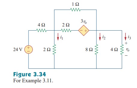
In the circuit of Fig. 3.34, determine the currents i_{1} , i_{2}   and   i_{3} .

تعليق توضيحي 2023-01-05 175945
Step-by-Step
The 'Blue Check Mark' means that this solution was answered by an expert.
Learn more on how do we answer questions.

The schematic is shown in Fig. 3.35. (The schematic in Fig. 3.35 includes the output results, implying that it is the schematic displayed on the screen after the simulation.) Notice that the voltage-controlled voltage source E1 in Fig. 3.35 is connected so that its input is the voltage across the 4-Ω resistor; its gain is set equal to 3. In order to display the required currents, we insert pseudocomponent IPROBES in the appropriate branches. The schematic is saved as exam311.sch and simulated by selecting Analysis/Simulate. The results are displayed on IPROBES as shown in Fig. 3.35 and saved in output file exam311.out. From the output file or the IPROBES, we obtain  i_{1} = i_{2} = 1.333 A   and   i_{3} = 2.667  A.

تعليق توضيحي 2023-01-05 180256

Related Answered Questions

Question: 3.2

Verified Answer:

The circuit in this example has three nonreference...
Question: 3.6

Verified Answer:

We apply KVL to the three meshes in turn. For mesh...
Question: 3.5

Verified Answer:

we first obtain the mesh currents using KVL. For m...
Question: 3.13

Verified Answer:

1. Define. The circuit is clearly defined and the ...
Question: 3.1

Verified Answer:

Consider Fig. 3.3(b), where the circuit in Fig. 3....
Question: 3.9

Verified Answer:

We have five meshes, so the resistance matrix is 5...
Question: 3.10

Verified Answer:

The first step is to draw the given circuit using ...
Question: 3.8

Verified Answer:

The circuit in Fig. 3.27 has four nonreference nod...
Question: 3.7

Verified Answer:

Note that meshes 1 and 2 form a supermesh since th...