Question 2.SP.29: For the full-wave rectifier circuit of Fig. 2-43(a), let vS ......
For the full-wave rectifier circuit of Fig. 2-43(a), let v_S = 120 \sqrt{2} \sin(120πt) \text{V}, R_S = 0.001 Ω, R_L = 5 Ω, and the ideal transformer has a turns ratio of 10:1. Using SPICE methods and assuming ideal diodes, plot the output voltage v_L and diode currents i_{D1} and i_{D2}. Compare the results with predicted values based on the solution of Problem 2.28.

Learn more on how do we answer questions.
The netlist code for analysis of the circuit is
| Prb2_29.CIR – FW rectifier vs 1 0 SIN( 0V {sqrt(2)*120V} 60Hz ) Rs 1 2 0.0010ohm * Ideal transformer, 10:1 ratio L1 2 0 1H IC=-0.39A L2 3 0 10mH L3 0 4 10mH kall L1 L2 L3 1 D1 3 5 DMOD D2 4 5 DMOD RL 5 0 5ohm .MODEL DMOD D(n=0.0001) ; Ideal diode .TRAN 1us 16.667ms 0s 1e-6s UIC .PROBE .END |
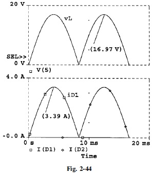
Execution of <Prb2_29.CIR> and use of the Probe feature of PSpice result in the plots of Fig. 2-44 where the peak values of v_L and i_{D1} have been marked.
Based on the results of Problem 2.28, the predicted peak values of v_L and i_{D1} are given by
i_{D1 \max} = \frac{v_{S \max}/n}{R_L} = \frac{120 \sqrt{2}/10}{5} = 3.39 \text{A}
v_{L \max} = \frac{v_{S \max}}{n} \frac{120 \sqrt{2}}{10} = 16.97 \text{V}
The predicted values and the SPICE results are in agreement.