Question 18.10: The portal frame shown in Fig. 18.20(a) has members which ha...
The portal frame shown in Fig. 18.20(a) has members which have the same plastic moment M_{\mathrm{P}}. Determine the minimum value of the load W required to cause collapse if the collapse mechanism is that shown in Fig. 18.20(b).

Learn more on how we answer questions.
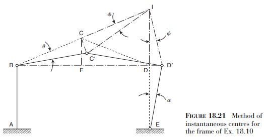
In Exs 18.8 and 18.9 the displacements of the joints of the frame were relatively simple to determine since all the members were perpendicular to each other. For a pitched roof frame the calculation is more difficult; one method is to use the concept of instantaneous centres.
In Fig. 18.21 the member \mathrm{BC} is given a small rotation \theta. Since \theta is small \mathrm{C} can be assumed to move at right angles to \mathrm{BC} to \mathrm{C}^{\prime}. Similarly the member DE rotates about \mathrm{E} so that \mathrm{D} moves horizontally to \mathrm{D}^{\prime}. Further, since \mathrm{C} moves at right angles to \mathrm{BC} and \mathrm{D} moves at right angles to \mathrm{DE} it follows that \mathrm{CD} rotates about the instantaneous centre, I, which is the point of intersection of BC and ED produced; the lines IC and ID then rotate through the same angle \phi.
From the triangles \mathrm{BCC}^{\prime} and \mathrm{ICC}^{\prime}
\mathrm{CC}^{\prime}=\mathrm{BC} \theta=\mathrm{IC} \phi
so that
\phi=\frac{\mathrm{BC}}{\mathrm{IC}}=\theta (i)
From the triangles \mathrm{EDD}^{\prime} and \mathrm{IDD}^{\prime}
\mathrm{DD}^{\prime}=\mathrm{ED} \alpha=\mathrm{ID} \phi
Therefore
\alpha=\frac{\mathrm{ID}}{\mathrm{ED}} \phi=\frac{\mathrm{ID}}{\mathrm{ED}} \frac{\mathrm{BC}}{\mathrm{IC}} \theta (ii)
Now we drop a perpendicular from \mathrm{C} to meet the horizontal through \mathrm{B} and \mathrm{D} at \mathrm{F}. Then, from the similar triangles BCF and BID
\frac{\mathrm{BC}}{\mathrm{CI}}=\frac{\mathrm{BF}}{\mathrm{FD}}=\frac{5}{5}=1
so that \mathrm{BC}=\mathrm{CI} and, from Eq. (i), \phi=\theta. Also
\frac{\mathrm{CF}}{\mathrm{ID}}=\frac{\mathrm{BF}}{\mathrm{BD}}=\frac{5}{10}=\frac{1}{2}
from which \mathrm{ID}=2 \mathrm{CF}=4 \mathrm{~m}. Then, from Eq. (ii)
\alpha=\frac{4}{5} \theta
Finally, the vertical displacement of \mathrm{C} {\text {to }} \mathrm{C}^{\prime} is \mathrm{BF} \theta(=5 \theta).
The equation of virtual work is then
W 5 \theta=M_{\mathrm{P}} \theta+M_{\mathrm{P}}(\theta+\alpha)+M_{\mathrm{P}}(\phi+\alpha)+M_{\mathrm{P}} \alpha
Substituting for \phi and \alpha in terms of \theta from the above gives
W=1.12 M_{\mathrm{P}}
The failure mechanism shown in Fig. 18.20(b) does not involve sway. If, however, a horizontal load were applied at B, say, then sway would occur and other possible failure mechanisms would have to be investigated; two such mechanisms are shown in Fig. 18.22. Note that in Fig. 18.22(a) there is a hinge cancellation at \mathrm{C} and in Fig. 18.22(b) there is a hinge cancellation at B. In determining the collapse loads of such frames the method of instantaneous centres still applies.