For the transmission line of Figure 11.27, calculate and sketch
(a) The voltage at the load and generator ends for 0\lt t\lt 6\mu s
(b) The current at the load and generator ends for 0\lt t\lt 6\mu s
For the transmission line of Figure 11.27, calculate and sketch
(a) The voltage at the load and generator ends for 0\lt t\lt 6\mu s
(b) The current at the load and generator ends for 0\lt t\lt 6\mu s

(a) We first calculate the voltage reflection coefficients at the generator and load ends:
\Gamma_{G}=\frac{Z_{g}-Z_{o}}{Z_{g}+Z_{o}}=\frac{100-50}{100+50}=\frac{1}{3}
\Gamma_{L}=\frac{Z_{L}-Z_{o}}{Z_{L}+Z_{o}}=\frac{200-50}{200+50}=\frac{3}{5}
The transit time
t_{1}=\frac{\ell}{u}=\frac{100}{10^{8}}=1\mu s
The initial voltage at the generator end is
V_{o}=\frac{Z_{o}}{Z_{o}+Z_{g}}V_{g}=\frac{50}{150}(12)=4V
The 4 V is sent out to the load. The leading edge of the pulse arrives at the load at t=t_{1}=1\mu s. A portion of it, 4(3/5) = 2.4 V, is reflected back and reaches the generator at t=2t_{1}=2\mu s. At the generator, 2.4(1/3) = 0.8 is reflected and the process continues. The whole process is best illustrated in the voltage bounce diagram of Figure 11.28.
From the bounce diagram, we can sketch V(0,t) and V(\ell,t) as functions of time as shown in Figure 11.29. Notice from Figure 11.29 that as t\rightarrow \infty, the voltages approach an asymptotic value of
V_{\infty}=\frac{Z_{L}}{Z_{L}+Z_{g}}V_{g}=\frac{200}{300}(12)=8V
This should be expected because the equivalent circuits at t=0 and t=\infty are as shown in Figure 11.30.
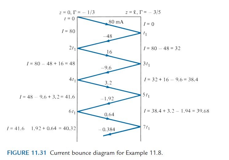
(b) The current reflection coefficients at the generator and load ends are
-\Gamma_{G}=-1/3
and
-\Gamma_{L}=-3/5
respectively. The initial current is
I_{o}=\frac{V_{o}}{Z_{o}}=\frac{4}{50}=80mA
Again, I(0,t) and I(\ell,t) are easily obtained from the current bounce diagram shown in Figure 11.31. These currents are sketched in Figure 11.32. Note that
I(\ell,t)=V(\ell,t)/Z_{L}
Hence, Figure 11.32(b) can be obtained either from the current bounce diagram of Figure 11.31 or by scaling Figure 11.29(b) by a factor of 1/Z_{L}=1/200.
Notice from Figures 11.30(b) and 11.32 that the currents approach an asymptotic value of
I_{\infty}=\frac{V_{g}}{Z_{g}+Z_{L}}=\frac{12}{300}=40mA