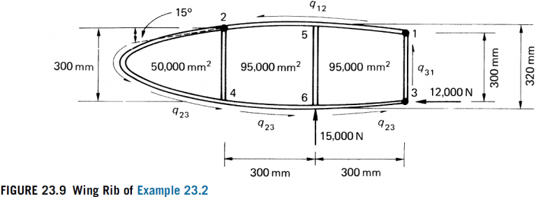
Calculate the shear flows in the web panels and the axial loads in the flanges of the wing rib shown in Fig. 23.9. Assume that the web of the rib is effective only in shear while the resistance of the wing to bending moments is provided entirely by the three flanges 1, 2, and 3.
Share
Share
Question 23.2: Calculate the shear flows in the web panels and the axial lo...
The Blue Check Mark means that this solution has been answered and checked by an expert. This guarantees that the final answer is accurate.
Learn more on how we answer questions.
Learn more on how we answer questions.
Since the wing bending moments are resisted entirely by the flanges 1, 2, and 3, the shear flows developed in the wing skin are constant between the flanges. Using the method described in Section 22.1 for a three-flange wing tion, we have, resolving forces horizontally,
600 q_{12}-600 q_{23}=12,000 N (i)
Resolving vertically,
300 q_{31}-300 q_{23}=15,000 N (ii)
Taking moments about flange 3,
2(50,000+95,000) q_{23}+2 \times 95,000 q_{12}=-15,000 \times 300 N mm (iii)
Solution of Eqs. (i)–(iii) gives
q_{12}=13.0 N / mm , q_{23}=-7.0 N / mm , q_{31}=43.0 N / mm
Consider now the nose portion of the rib shown in Fig. 23.10 and suppose that the shear flow in the web immediately to the left of the stiffener 24 is q_{1}. The total vertical shear force S_{y, 1} at this section is given by
S_{y, 1}=7.0 \times 300=2,100 N
The horizontal components of the rib flange loads resist the bending moment at this section. Thus,
P_{x, 4}=P_{x, 2}=\frac{2 \times 50,000 \times 7.0}{300}=2,333.3 N
The corresponding vertical components are then
P_{y, 2}=P_{y, 4}=2,333.3 \tan 15^{\circ}=625.2 N
Thus, the shear force carried by the web is 2,100-2 \times 625.2=849.6 N. Hence,
q_{1}=\frac{849.6}{300}=2.8 N / mm
The axial loads in the rib flanges at this section are given by
P_{2}=P_{4}=\left(2,333.3^{2}+625.2^{2}\right)^{1 / 2}=2,415.6 N
The rib flange loads and web panel shear flows, at a vertical section immediately to the left of the intermediate web stiffener 56, are found by considering the free body diagram shown in Fig. 23.11. At this section, the rib flanges have zero slope, so that the flange loads P_{5} and P_{6} are obtained directly from the value of bending moment at this section. Thus,
P_{5}=P_{6}=2[(50,000+46,000) \times 7.0-49,000 \times 13.0] / 320=218.8 N
The shear force at this section is resisted solely by the web. Hence,
320 q_{2}=7.0 \times 300+7.0 \times 10-13.0 \times 10=2,040 N
so that
q_{2}=6.4 N / mm
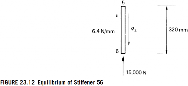
The shear flow in the rib immediately to the right of stiffener 56 is found most simply by considering the vertical equilibrium of stiffener 56, as shown in Fig. 23.12. Thus,
320 q_{3}=6.4 \times 320+15,000
which gives
q_{3}=53.3 N / mm
Finally, we consider the rib flange loads and the web shear flow at a section immediately forward of stiffener 31. From Fig. 23.13, in which we take moments about the point 3,
M_{3}=2[(50,000+95,000) \times 7.0-95,000 \times 13.0]+15,000 \times 300=4.06 \times 10^{6} N mm
The horizontal components of the flange loads at this section are then
P_{x, 1}=P_{x, 3}=\frac{4.06 \times 10^{6}}{300}=13,533.3 N
and the vertical components are
P_{y, 1}=P_{y, 3}=3,626.2 N
Hence,
P_{1}=P_{3}=\sqrt{13,533.3^{2}+3,626.2^{2}}=14,010.7 N
The total shear force at this section is 15,000+300 \times 7.0=17,100 N. Therefore, the shear force resisted by the web is 17,100-2 \times 3,626.2=9,847.6 N, so that the shear flow q_{3} in the web at this section is
q_{3}=\frac{9,847.6}{300}=32.8 N / mm