(a) Determine the unloaded output voltage of the voltage divider in Figure 7-30.
(b) Find the loaded output voltages of the voltage divider in Figure 7-30 for the following two values of load resistance: R_{L} = 10 kΩ and R_{L} = 100 kΩ.
(a) Determine the unloaded output voltage of the voltage divider in Figure 7-30.
(b) Find the loaded output voltages of the voltage divider in Figure 7-30 for the following two values of load resistance: R_{L} = 10 kΩ and R_{L} = 100 kΩ.

(a) The unloaded output voltage is
V_{OUT(unloaded)} = \left(\frac{R_{2}}{R_{1}+ R_{2}} \right)V_{S}= \left(\frac{10 \ k \Omega }{14.7 \ k\Omega } \right) 5 \ V= 3.40 \ V(b) With the 10 kΩ load resistor connected, R_{L} is in parallel with R_{2} which gives
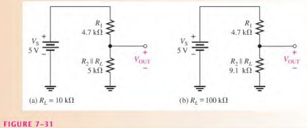
R_{2}\parallel R_{L}= \frac{R_{2}R_{L}}{R_{2}+ R_{L}}= \frac{100 \ M\Omega }{20 \ k\Omega } = 5 \ K\OmegaThe equivalent circuit is shown in Figure 7-31 (a). The loaded output voltage is
V_{OUT(loaded)} = \left(\frac{R_{2}|| R_{L}}{R_{1}+ R_{2} || R_{L}} \right)V_{S}= \left(\frac{5 \ k \Omega }{9.7 \ k\Omega } \right) 5 \ V= 2.58 \ VWith the 100 kΩ load, the resistance from output to ground is
R_{2}\parallel R_{L}= \frac{R_{2}R_{L}}{R_{2}+ R_{L}}= \frac{(10 \ kΩ ) (100 \ kΩ ) }{110 \ kΩ} = 9.1 \ K\OmegaThe equivalent circuit is shown in Figure 7-31(b). The loaded output voltage is
V_{OUT(loaded)} = \left(\frac{R_{2}|| R_{L}}{R_{1}+ R_{2} || R_{L}} \right)V_{S}= \left(\frac{9.1 \ k \Omega }{13.8 \ k\Omega } \right) 5 \ V= 3.30 \ VFor the smaller value of R_{L}, the reduction in V_{OUT} is
3.40 V — 2.58 V = 0.82 V (a 24% drop in output voltage)
For the larger value of R_{L}, the reduction in V_{OUT} is
3.40 V – 3.30 V = 0.10 V (a 3% drop in output voltage)
This illustrates the loading effect of R_{L}, on the voltage divider.