A 17-tooth 20° pressure angle spur pinion rotates at 1800 rev/min and transmits 4 hp to a 52-tooth disk gear. The diametral pitch is 10 teeth/in, the face width 1.5 in, and the quality standard is No. 6. The gears are straddle-mounted with bearings immediately adjacent. The pinion is a grade 1 steel with a hardness of 240 Brinell tooth surface and through-hardened core. The gear is steel, through-hardened also, grade 1 material, with a Brinell hardness of 200, tooth surface and core. Poisson’s ratio is 0.30, J_P=0.30, J_G=0.40, and Young’s modulus is 30(10^6) psi. The loading is smooth because of motor and load. Assume a pinion life of 10^8 cycles and a reliability of 0.90, and use Y_N=0.3558N^{-0.0178}, Z_N=1.4488N^{-0.023}. The tooth profile is uncrowned. This is a commercial enclosed gear unit.
(a) Find the factor of safety of the gears in bending.
(b) Find the factor of safety of the gears in wear.
(c) By examining the factors of safety, identify the threat to each gear and to the mesh.
Question 14.4: A 17-tooth 20° pressure angle spur pinion rotates at 1800 re...
Learn more on how we answer questions.
There will be many terms to obtain so use Figs. 14–17 and 14–18 as guides to what is needed.
d_P = N_P/P_d = 17/10 = 1.7 in d_G = 52/10 = 5.2 in
V=\frac{\pi d_Pn_P}{12}=\frac{\pi (1.7)1800}{12}=801.1 ft/min
W^t=\frac{33 000 H}{V}=\frac{33 000(4)}{801.1}= 164.8 lbf
Assuming uniform loading, K_o = 1. To evaluate K_v, from Eq. (14–28) with a quality number Q_v = 6,
A = 50 + 56(1 – B)
B = 0.25(12 – Q_v)^{2/3} (14.28)
B = 0.25(12 – 6)^{2/3} = 0.8255
A = 50 + 56(1 – 0.8255) = 59.77
Then from Eq. (14–27)
K_v=\begin{cases}\left(\frac{A+\sqrt{V} }{A} \right)^B & V in ft/min \\ \left(\frac{A+\sqrt{200V} }{A} \right)^B & V in m/s \end{cases} (14.27)
the dynamic factor is
K_v=\left(\frac{59.77+\sqrt{801.1} }{59.77} \right)^{0.8255}=1.377
To determine the size factor, K_s, the Lewis form factor is needed. From Table 14–2,
| Number of Teeth |
Y | Number of Teeth |
Y |
| 12 | 0.245 | 28 | 0.353 |
| 13 | 0.261 | 30 | 0.359 |
| 14 | 0.277 | 34 | 0.371 |
| 15 | 0.29 | 38 | 0.384 |
| 16 | 0.296 | 43 | 0.397 |
| 17 | 0.303 | 50 | 0.409 |
| 18 | 0.309 | 60 | 0.422 |
| 19 | 0.314 | 75 | 0.435 |
| 20 | 0.322 | 100 | 0.447 |
| 21 | 0.328 | 150 | 0.460 |
| 22 | 0.331 | 300 | 0.472 |
| 24 | 0.337 | 400 | 0.480 |
| 26 | 0.346 | Rack | 0.485 |
with N_P = 17 teeth, Y_P = 0.303. Interpolation for the gear with N_G = 52 teeth yields Y_G = 0.412. Thus from Eq. (a) of Sec. 14–10, with F = 1.5 in,
(K_S)_P=1.192\left(\frac{1.5\sqrt{0.303} }{10} \right)^{0.0535}=1.043
(K_S)_G=1.192\left(\frac{1.5\sqrt{0.412} }{10} \right)^{0.0535}=1.052
The load distribution factor K_m is determined from Eq. (14–30),
K_m = C_{mf} = 1 + C_{mc}(C_{pf} C_{pm} + C_{ma} C_e)
where five terms are needed. They are, where F = 1.5 in when needed:
Uncrowned, Eq. (14–30): C_{mc} = 1,
Eq. (14–32):
C_{pf}= \begin{cases} \frac{F}{10d_P}-0.025 & F \leq 1 in \\ \frac{F}{10d_P}-0.0375+0.0125F & 1\lt F\leq 17 in\\ \frac{F}{10d_P}-0.1109+0.0207F-0.000 228F^2 & 17\lt F\leq 40 in \end{cases} (14.32)
C_{pf} = 1.5/[10(1.7)] – 0.0375 + 0.0125(1.5) = 0.0695
Bearings immediately adjacent, Eq. (14–33):
C_{pm}= \begin{cases} 1 & for straddle-mounted pinion with S_1/S \lt 0.175 \\ 1.1 & for straddle-mounted pinion with S_1/S \geq 0.175 \end{cases} (14.33)
C_{pm} = 1
Commercial enclosed gear units (Fig. 14–11): C_{ma} = 0.15
Eq. (14–35):
C_{e}= \begin{cases} 0.8 & for gearing adjusted at assembly, or compatibility is improved by lapping, or both \\ 1 & for all other conditions \end{cases} (14.35)
C_e = 1
Thus,
K_m = 1 + C_{mc}(C_{pf} C_{pm} + C_{ma}C_{e}) = 1 + (1) [0.0695(1) + 0.15(1) ] = 1.22
Assuming constant thickness gears, the rim-thickness factor K_B = 1. The speed ratio is m_G = N_G/N_P = 5217 = 3.059. The load cycle factors given in the problem statement, with N(pinion) = 10^8 cycles and N(gear) = 10^8/m_G = 10^8/3.059 cycles, are
(Y_N)_P=1.3558(10^8)^{-0.0178}=0.977
(Y_N)_G=1.3558(10^8/3.059)^{-0.0178}=0.996
From Table 14.10,
| Reliability | K_R (Y_Z) |
| 0.9999 | 1.50 |
| 0.999 | 1.25 |
| 0.99 | 1.00 |
| 0.90 | 0.85 |
| 0.50 | 0.70 |
with a reliability of 0.9, K_R = 0.85. From Fig. 14–18, the temperature and surface condition factors are K_T = 1 and C_f = 1. From Eq. (14–23),
I= \begin{cases} \frac{\cos \phi_t \sin \phi_t}{2m_N} \frac{m_G}{m_G+1} & external gears \\ \frac{\cos \phi_t \sin \phi_t}{2m_N} \frac{m_G}{m_G-1} & internal gears \end{cases} (14.23)
with m_N = 1 for spur gears,
I=\frac{\cos 20° \sin 20°}{2}\frac{3.059}{3.059+1}=0.121
From Table 14–8, C_p = 2300\sqrt{psi}.
Next, we need the terms for the gear endurance strength equations. From Table 14–3,
for grade 1 steel with H_{BP} = 240 and H_{BG} = 200, we use Fig. 14–2, which gives
(S_t)_P = 77.3(240) + 12 800 = 31 350 psi
(S_t)_G = 77.3(200) + 12 800 = 28 260 psi
Similarly, from Table 14–6, we use Fig. 14–5, which gives
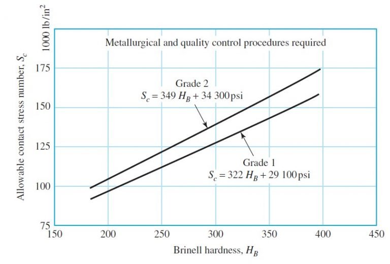
(S_c)_P = 322(240) + 29 100 = 106 400 psi
(S_c)_G = 322(200) + 29 100 = 93 500 psi
From Fig. 14–15,
(Z_N)_P = 1.4488(10^8)^{-0.023} = 0.948
(Z_N)_G = 1.4488(10^8/3.059)^{-0.023} = 0.973
For the hardness ratio factor C_H, the hardness ratio is H_{BP}/H_{BG} = 240/200 = 1.2. Then, from Sec. 14–12,
A' = 8.98(10^{-3})(H_{BP}/H_{BG}) – 8.29(10^{-3})
= 8.98(10^{-3})(1.2) – 8.29(10{-3}) = 0.002 49
Thus, from Eq. (14–36),
C_H=1.0+A'(m_G-1.0) (14.36)
C_H = 1 + 0.002 49(3.059 – 1) = 1.005
(a) Pinion tooth bending. Substituting the appropriate terms for the pinion into Eq. (14–15) gives
(\sigma )_P=\left(W^tK_oK_vK_s\frac{P_d}{F}\frac{K_mK_B}{J} \right)_P= 164.8(1)1.377(1.043)\frac{10}{1.5}\frac{1.22(1)}{0.30}
= 6417 psi
Substituting the appropriate terms for the pinion into Eq. (14–41) gives
(S_F)_P=\left(\frac{S_tY_N/(K_TK_R)}{\sigma } \right)_P =\frac{31 350(0.977)/[1(0.85)]}{6417} = 5.62
Gear tooth bending. Substituting the appropriate terms for the gear into Eq. (14–15)
gives
(\sigma )_G=164.8(1)1.377(1.052)\frac{10}{1.5}\frac{1.22(1)}{0.40}=4854 psi
Substituting the appropriate terms for the gear into Eq. (14–41) gives
(S_F)_G=\frac{28 260(0.996)/[1(0.85)]}{4854}=6.82
(b) Pinion tooth wear. Substituting the appropriate terms for the pinion into Eq. (14–16)
gives
(\sigma )_P=\left(W^tK_oK_vK_s\frac{K_m}{d_PF}\frac{C_f}{I} \right)^{1/2}_P
=2300\left[164.8(1)1.377(1.043)\frac{1.22}{1.7(1.5)}\frac{1}{0.121} \right]^{1/2}=70 360 psi
Substituting the appropriate terms for the pinion into Eq. (14–42) gives
(S_H)_P=\left[\frac{S_CZ_N/(K_TK_R)}{\sigma _C} \right]_P=\frac{106 400(0.948)/[1(0.85)]}{70 360}=1.69
Gear tooth wear. The only term in Eq. (14–16) that changes for the gear is K_s. Thus,
(\sigma _c)_G=\left[\frac{(K_S)_G}{(K_S)_P} \right]^{1/2} (\sigma _c)_P=\left(\frac{1.052}{1.043} \right)^{1/2} 70 360 = 70 660 psi
Substituting the appropriate terms for the gear into Eq. (14–42) with C_H = 1.005 gives
(S_H)_G=\frac{93 500(0.973)1.005/[1(0.85)]}{70 660}=1.52
(c) For the pinion, we compare (S_F)_P with (S_H)^2_P, or 5.73 with 1.69^2 = 2.86, so the threat in the pinion is from wear. For the gear, we compare (S_F)_G with (S_H)^2 _G, or 6.96 with 1.52^2 = 2.31, so the threat in the gear is also from wear.