Convert the parallel circuit in Figure 15-49 to a series form.
Share
Share
Question 15.20: Convert the parallel circuit in Figure 15-49 to a series for...

The Blue Check Mark means that this solution has been answered and checked by an expert. This guarantees that the final answer is accurate.
Learn more on how we answer questions.
Learn more on how we answer questions.
First, find the admittance of the parallel circuit as follows:
G=\frac{1}{R}= \frac{1}{18 \ k\Omega }= 55.6 \ \mu SB_{C}=\frac{1}{X_{C}}= \frac{1}{27 \ k\Omega }= 37.0 \ \mu S
Y = G + jB_{C} = 55.6 \mu S + 37.0 \mu S
Converting to polar form yields
Y= \sqrt{G^{2}+ B^{2}_{C}} \angle \tan ^{-1} \left (\frac{B_{C}}{G} \right)\ \ \ \ \ = \sqrt{(55.6 \ \mu S)^{2}+ (37.0 \ \mu S)^{2}} \angle \tan ^{-1} \left(\frac{37.0 \ \mu S}{55.6 \ \mu S} \right)= 66.8 \angle 33.6° \mu S
Then, the total impedance is
Z_{tot}= \frac{1}{Y}=\frac{1}{66.8 \angle 33.6° \mu S}= 15.0 \angle -33.6° \ K\OmegaConverting to rectangular form yields
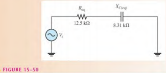
Z_{tot}= Z\cos \theta – jZ\sin \theta = R_{eq}- jX_{C(eq)}\ \ \ \ \ \ = 15.0 \ k\Omega \cos (-33.6°)- j15.0 \ k\Omega \sin (-33.6°)= 12.5 \ k\Omega – j8.31 \ k\Omega
The equivalent series RC circuit is a 12.5 kΩ resistor in series with a capacitive reactance of 8.31 kΩ. This is shown in Figure 15-50.
Related Answered Questions
The effective circuit resistance is
R_{th}=...
Apply the APM method to this troubleshooting probl...
f_{r}= \frac{1}{2\pi \sqrt{6}RC }= \frac{1}...
The resistor current, the capacitor current, and t...
(a) First, calculate the magnitudes of capacitive ...
First, calculate X_{C1} and ...
The capacitive reactance is
X_{C}= \frac{1}...
The capacitive reactance and currents through R an...
The capaeitive reactance is
X_{C}= \frac{1}...
For the lead circuit in Figure 15-35(a),
\p...