Here we follow the procedure of estimating the strengths and then the stresses, followed by relating the two.
From Table A–20
Table A–20
Deterministic ASTM Minimum Tensile and Yield Strengths for Some Hot-Rolled (HR) and Cold-Drawn (CD) Steels [The strengths listed are estimated ASTM minimum values in the size range 18 to 32 mm (\frac{3}{4} \text { to } 1 \frac{1}{4} \text { in ). }. These strengths are suitable for use with the design factor defined in Sec. 1–10, provided the materials conform to ASTM A6 or A568 requirements or are required in the purchase specifications. Remember that a numbering system is not a specification.] Source: 1986 SAE Handbook, p. 2.15. |
| 1 |
2 |
3 |
4 |
5 |
6 |
7 |
8 |
|
|
|
Tensile
MPa (kpsi)
Strength, |
Yield Strength,
MPa (kpsi) |
Elongation in
2 in, % |
|
|
| UNS No. |
SAE and/or
AISI No. |
Processing |
Reduction in
Area, % |
Brinell
Hardness |
| G10060 |
1006 |
HR |
300 (43) |
170 (24) |
30 |
55 |
86 |
|
|
CD |
330 (48) |
280 (41) |
20 |
45 |
95 |
| G10100 |
1010 |
HR |
320 (47) |
180 (26) |
28 |
50 |
95 |
|
|
CD |
370 (53) |
300 (44) |
20 |
40 |
105 |
| G10150 |
1015 |
HR |
340 (50) |
190 (27.5) |
28 |
50 |
101 |
|
|
CD |
390 (56) |
320 (47) |
18 |
40 |
111 |
| G10180 |
1018 |
HR |
400 (58) |
220 (32) |
25 |
50 |
116 |
|
|
CD |
440 (64) |
370 (54) |
15 |
40 |
126 |
| G10200 |
1020 |
HR |
380 (55) |
210 (30) |
25 |
50 |
111 |
|
|
CD |
470 (68) |
390 (57) |
15 |
40 |
131 |
| G10300 |
1030 |
HR |
470 (68) |
260 (37.5) |
25 |
42 |
137 |
|
|
CD |
520 (76) |
440 (64) |
15 |
35 |
149 |
| G10350 |
1035 |
HR |
500 (72) |
270 (39.5) |
20 |
40 |
143 |
|
|
CD |
550 (80) |
460 (67) |
12 |
35 |
163 |
| G10400 |
1040 |
HR |
520 (76) |
290 (42) |
18 |
40 |
149 |
|
|
CD |
590 (85) |
490 (71) |
12 |
35 |
170 |
| G10450 |
1050 |
HR |
570 (82) |
310 (45) |
16 |
40 |
163 |
|
|
CD |
630 (91) |
530 (77) |
12 |
35 |
179 |
| G10500 |
1060 |
HR |
620 (90) |
340 (49.5) |
15 |
35 |
179 |
|
|
CD |
690 (100) |
580 (84) |
10 |
30 |
197 |
| G10600 |
1060 |
HR |
680 (98) |
370 (54) |
12 |
30 |
201 |
| G10800 |
1080 |
CD |
770 (112) |
420 (61.5) |
10 |
25 |
229 |
| G10950 |
1095 |
HR |
830 (120) |
460 (66) |
10 |
25 |
248 |
we find the minimum strengths to be S_{ut}= 440 \ MPa \ and \ S_y=370 \ MPa.
The endurance limit of the rotating-beam specimen is 0.5\left(440\right) = 220 \ MPa.
The surface factor, obtained from Eq. (6–19)
K_a=aS^B_{ut}
and Table 6–2, p. 287, is
| Table 6–2 Parameters for Marin Surface Modification Factor, Eq. (6–19) |
| Surface Finish |
Factor a |
Exponent
b |
| S{ut}, kpsi |
S{ut} , MPa |
| Ground |
1.34 |
1.58 |
−0.085 |
| Machined or cold-drawn |
2.7 |
4.51 |
−0.265 |
| Hot-rolled |
14.4 |
57.7 |
−0.718 |
| As-forged |
39.9 |
272 |
−0.995 |
is
K_a=1.51S^{-0.265}_{ut}=4.51\left(440\right) ^{-0.265}=0.899
From Eq. (6–20)
k_{b}=\left\{\begin{array}{ll}(d / 0.3)^{-0.107}=0.879 d^{-0.107} & 0.11 \leq d \leq 2 \text { in } \\0.91 d^{-0.157} & 2<d \leq 10 \text { in } \\(d / 7.62)^{-0.107}=1.24 d^{-0.107} & 2.79 \leq d \leq 51 \mathrm{~mm} \\1.51 d^{-0.157} & 51<d \leq 254 \mathrm{~mm} \end{array}\right.
the size factor is
k_b=\left(\frac{d}{7.62} \right) ^{-0.107}=\left(\frac{42}{7.62} \right)^{-0.107} =0.833
The remaining Marin factors are all unity, so the modified endurance strength S_e is
S_e=0.899\left(0.833\right) 220=165 MPa
(a) Theoretical stress-concentration factors are found from Table A–16.
| Table A–16 Approximate Stress- Concentration Factor K_t for Bending of a Round Bar or Tube with a Transverse Round Hole Source: R. E. Peterson, Stress-Concentration Factors, Wiley,New York, 1974, pp. 146, 235 |
| The nominal bending stress is\sigma _0= M/Znet where Z_{net} is a reduced value of the section modulus and is defined by |
| Z_{net}=\frac{\pi A }{32D} \left(D^4-d^4\right) |
 |
| Values of A are listed in the table. Use d = 0 for a solid bar |
| {d}/{D} |
| {a}/{D} |
A |
K_{t} |
A |
K_{t} |
A |
K_{t} |
| 0.050 |
0.92 |
2.63 |
0.91 |
2.55 |
0.88 |
2.42 |
| 0.075 |
0.89 |
2.55 |
0.88 |
2.43 |
0.86 |
2.35 |
| 0.100 |
0.86 |
2.49 |
0.85 |
2.36 |
0.83 |
2.27 |
| 0.125 |
0.82 |
2.41 |
0.82 |
2.32 |
0.80 |
2.20 |
| 0.15 |
0.79 |
2.39 |
0.79 |
2.29 |
0.76 |
2.15 |
| 0.175 |
0.76 |
2.38 |
0.75 |
2.26 |
0.72 |
2.10 |
| 0.20 |
0.73 |
2.39 |
0.72 |
2.23 |
0.68 |
2.07 |
| 0.225 |
0.69 |
2.40 |
0.68 |
2.21 |
0.65 |
2.04 |
| 0.25 |
0.67 |
2.42 |
0.64 |
2.18 |
0.61 |
2.00 |
| 0.275 |
0.66 |
2.48 |
0.61 |
2.16 |
0.58 |
1.97 |
| 0.30 |
0.64 |
2.52 |
0.58 |
2.14 |
0.54 |
1.94 |
Using {a}/{D} ={6}/{4}2 = 0.143 \ and {d}/{D} = {34}/{42} = 0.810,
and using linear interpolation, we obtain A = 0.798 \ and \ K_t= 2.366 \ for \ bending \ ; \ and \ A = 0.89 \ and \ K_{ts}=1.75 for torsion.
Thus, for bending,
Z_{net}=\frac{\pi A }{32D} \left(D^4-d^4\right)=\frac{\pi \left(0.798\right) }{32\left(42\right) } \left[\left(42\right)^4-\left(34\right)^4 \right] =3.31\left(10^3\right) \ mm^3
and for torsion
J_{net}=\frac{\pi A }{32} \left(D^4-d^4\right)=\frac{\pi \left(0.8\right) }{32\left(42\right) } \left[\left(42\right)^4-\left(34\right)^4 \right] =155\left(10^3\right) \ mm^4
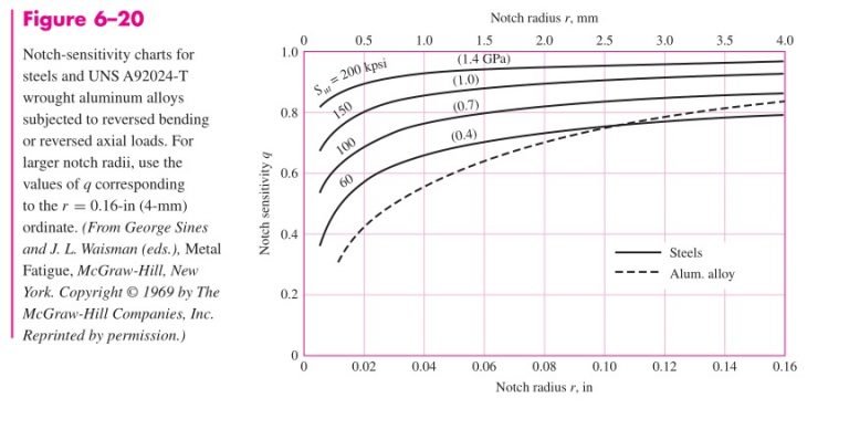
Next, using Figs. 6–20 and 6–21, pp. 295–296, with a notch radius of 3 mm we find the notch sensitivities to be 0.78 for bending and 0.81 for torsion.
The two corresponding fatigue stress-concentration factors are obtained from Eq. (6–32)
K_f=1+q\left(K_t-1\right) or K_{fs}=1+q_{shear}\left(K_{ts}-1\right)
as
K_f=1+q\left(K_t-1\right)=K_f=1+0.78\left(2.366-1\right)=2.07
K_{fs}=1+0.81\left(1.75-1\right)=1.61
The alternating bending stress is now found to be
\sigma _{xa}=K_f\frac{M}{Z_{net}} =2.07\frac{150}{3.31\left(10^{-6}\right) } =93.8\left(10^6\right) \ Pa=93.8 \ MPa
and the alternating torsional stress is
\tau _{xya}= K_{fs}\frac{TD}{2J_{net}} =1.61\frac{120\left(42\right)\left(10^{-3}\right) }{2\left(155\right)\left(10^{-9}\right) } =26.2\left(10^6\right) \ Pa= 26.2 \ MPa
The midrange von Mises component \sigma '_m is zero. The alternating component \sigma '_m is given by
\sigma '_a=\left(\sigma ^2_{xa}+3\tau ^2_{xya}\right)^{{1}/{2}}=\left[93.8^2+3\left(26.2^2\right) \right]^{{1}/{2}}=104.2 \ MPa
Since S_e= S_a, the fatigue factor of safety n_f is
n_f=\frac{S_a}{\sigma '_a} =\frac{165}{104.2} =1.58
The first-cycle yield factor of safety is
n_y=\frac{S_y}{\sigma '_a} =\frac{370}{105.6} =3.50
There is no localized yielding; the threat is from fatigue. See Fig. 6–32.
(b) This part asks us to find the factors of safety when the alternating component is due to pulsating torsion, and a steady component is due to both torsion and bending.
We have T_a={\left(160-20\right) }/{2}=70 \ N.m \ and \ T_m={\left(160+20\right) }/{2}=90 \ N.m.
The corresponding amplitude and steady-stress components are
\tau _{xya}=K_{fs}\frac{T_aD}{2J_{net}} =1.61\frac{70\left(42\right)\left(10^{-3}\right) }{2\left(155\right)\left(10^{-9}\right) } =15.3 (10^6) pa =15.3 \ MPa
\tau _{xym}=K_{fs}\frac{T_mD}{2J_{net}} =1.61\frac{90\left(42\right)\left(10^{-3}\right) }{2\left(155\right)\left(10^{-9}\right) } =19.7 (10^6) pa = 19.7 \ MPa
The steady bending stress component \sigma _{xm} is
\sigma _{xm}=K_f=\frac{M_m}{Z_{net}} =2.07\frac{150}{3.31\left(10^{-6}\right)} =93.8\left(10^6\right) \ Pa=93.8 \ MPa
The von Mises components \sigma' _a \ and \sigma' _m are
\sigma' _a=\left[3\left(15.3\right)^2 \right] ^{{1}/{2}}=26.5 \ MPa.
\sigma' _m=\left[93.8^2+3\left(19.7\right)^2 \right] ^{{1}/{2}}=99.8 \ MPa
From Table 6–7, p. 307,
Table 6–7
Amplitude and Steady Coordinates of Strength and Important
Intersections in First Quadrant for Gerber and Langer Failure Criteria |
| Intersecting Equations |
Intersection Coordinates |
\frac{S_a}{S_e} +\left(\frac{S_m}{S_{ut}}\right)^2 =1
Load liner=\frac{S_a}{S_m} |
S_a=\frac{r^2S^2_{ut}}{S_e} \left[-1+\sqrt{1+\left(\frac{2S_e}{rS_{ut}} \right)^2 } \right]
S_m=\frac{S_a}{r} |
\frac{S_a}{S_y} +\frac{S_m}{S_y} =1
Load liner=\frac{S_a}{S_m} |
S_a=\frac{rS_y}{1+r}
S_m=\frac{rS_y}{1+r} |
\frac{S_a}{S_e} +\left(\frac{S_m}{S_{ut}}\right)^2 =1
\frac{S_a}{S_y} +\frac{S_m}{S_y} =1 |
S_m=\frac{2S^2_{ut}}{2S_e} \left[1-\sqrt{1+\left(\frac{2S_e}{S_{ut}} \right)^2 \left(1-\frac{S_y}{S_e} \right) } \right]
S_{a} = S_{y} – S _{m} , r_{crit}={S_a}/{S_m} |
Fatigue factor of safety
n_f=\frac{1}{2} \left(\frac{S_{ut}}{\sigma _m} \right)^2\frac{\sigma _a}{S_e}\left[-1+\sqrt{1+\left(\frac{2\sigma _mS_e}{S_{ut}\sigma _a} \right)^2 } \right] \ \sigma _m\gt 0 |
the fatigue factor of safety is
n_f=\frac{1}{2}\left(\frac{440}{99.8} \right) ^2\frac{26.5}{165} \left\{-1+\sqrt{1+\left[\frac{2\left(99.8\right)165 }{440\left(26.5\right) } \right]^2 } \right\} =3.12
From the same table, with r={\sigma '_a}/{\sigma'_m}={26.5}/{99.8}=0.28 , the strengths can be shownto be S_a= 85.5 \ MPa \ and \ S_m= 305 \ MPa.
See the plot in Fig. 6–32.
The first-cycle yield factor of safety n_y is
n_y=\frac{S_y}{\sigma '_a+\sigma '_m} =\frac{370}{26.5+99.8} =2.93
There is no notch yielding. The likelihood of failure may first come from first-cycle yielding at the notch. See the plot in Fig. 6–32.