A part of a conveyor system for a production operation is shown in Figure 5–17. The complete system will include several hundred hanger assemblies like this one. Design the horizontal bar that extends between two adjacent conveyor hangers and that supports a fixture at its midpoint. The empty fixture weighs 85 lb. A cast iron engine block weighing 225 lb is hung on the fixture to carry it from one process to another, where it is then removed. It is expected that the bar will experience several thousand cycles of loading and unloading of the engine blocks. Design Example 5–2 considered this same system with the objective of specifying the diameter of the pins. The pin at the middle of the horizontal bar where the fixture is hung has been specified to have a diameter of 0.50 in. Those at each end where the horizontal bar is connected to the conveyor hangers are each 0.375 in.

Objective: Design the horizontal bar for the conveyor system.
Given: The general arrangement is shown in Figure 5–17. The bar is simply supported at points 24 in apart. A vertical load that is alternately 85 lb and 310 lb (85 + 225) is applied at the middle of the bar through the pin connecting the fixture to the bar. The load will cycle between these two values many thousands of times in the expected life of the bar. The pin at the middle of the bar has a diameter of 0.50 in, while the pins at each end are 0.375 in.
Basic Design Decisions:
It is proposed to make the bar from steel in the form of a rectangular bar with the long dimension of its cross section vertical. Cylindrical holes will be machined on the neutral axis of the bar at the support points and at its center to receive cylindrical pins that will attach the bar to the conveyor carriers and to the fixture. Figure 5–18 shows the basic design for the bar.
The thickness of the bar, t, should be fairly large to provide a good bearing surface for the pins and to ensure lateral stability of the bar when subjected to the bending stress. A relatively thin bar would tend to buckle along its top surface where the stress is compressive. As a design decision, we will use a thickness of t = 0.50 in. The design analysis will determine the required height of the bar, h, assuming that the primary mode of failure is stress due to bending. Other possible modes of failure are discussed in the comments at the end of this example.
An inexpensive steel is desirable because several hundred bars will be made. We specify SAE 1020 hot-rolled steel having a yield strength of s_y = 30 ksi and an ultimate strength of s_u = 55 ksi (Appendix 3).
| APPENDIX 3 Design Properties of Carbon and Alloy Steel | |||||||
| Material designation (SAE number) |
Condition | Tensile strength |
Yield strength |
Ductility (percent elongation in 2 in) |
Brinell hardness (HB) |
||
| (ksi) | (MPa) | (ksi) | (MPa) | ||||
| 1020 | Hot-rolled | 55 | 379 | 30 | 207 | 25 | 111 |
| 1020 | Cold-drawn | 61 | 420 | 51 | 352 | 15 | 122 |
| 1020 | Annealed | 60 | 414 | 43 | 296 | 38 | 121 |
| 1040 | Hot-rolled | 72 | 496 | 42 | 290 | 18 | 144 |
| 1040 | Cold-drawn | 80 | 552 | 71 | 490 | 12 | 160 |
| 1040 | OQT 1300 | 88 | 607 | 61 | 421 | 33 | 183 |
| 1040 | OQT 400 | 113 | 779 | 87 | 600 | 19 | 262 |
| 1050 | Hot-rolled | 90 | 620 | 49 | 338 | 15 | 180 |
| 1050 | Cold-drawn | 100 | 690 | 84 | 579 | 10 | 200 |
| 1050 | OQT 1300 | 96 | 662 | 61 | 421 | 30 | 192 |
| 1050 | OQT 400 | 143 | 986 | 110 | 758 | 10 | 321 |
| 1117 | Hot-rolled | 65 | 448 | 40 | 276 | 33 | 124 |
| 1117 | Cold-drawn | 80 | 552 | 65 | 448 | 20 | 138 |
| 1117 | WQT 350 | 89 | 614 | 50 | 345 | 22 | 178 |
| 1137 | Hot-rolled | 88 | 607 | 48 | 331 | 15 | 176 |
| 1137 | Cold-drawn | 98 | 676 | 82 | 565 | 10 | 196 |
| 1137 | OQT 1300 | 87 | 600 | 60 | 414 | 28 | 174 |
| 1137 | OQT 400 | 157 | 1083 | 136 | 938 | 5 | 352 |
| 1144 | Hot-rolled | 94 | 648 | 51 | 352 | 15 | 188 |
| 1144 | Cold-drawn | 100 | 690 | 90 | 621 | 10 | 200 |
| 1144 | OQT 1300 | 96 | 662 | 68 | 496 | 25 | 200 |
| 1144 | OQT 400 | 127 | 876 | 91 | 627 | 16 | 277 |
| 1213 | Hot-rolled | 55 | 379 | 33 | 228 | 25 | 110 |
| 1213 | Cold-drawn | 75 | 517 | 58 | 340 | 10 | 150 |
| 12L13 | Hot-rolled | 57 | 393 | 34 | 234 | 22 | 114 |
| 12L13 | Cold-drawn | 70 | 483 | 60 | 414 | 10 | 140 |
| 1340 | Annealed | 102 | 703 | 63 | 434 | 26 | 207 |
| 1340 | OQT 1300 | 100 | 690 | 75 | 517 | 25 | 235 |
| 1340 | OQT 1000 | 144 | 993 | 132 | 910 | 17 | 363 |
| 1340 | OQT 700 | 221 | 1520 | 197 | 1360 | 10 | 444 |
| 1340 | OQT 400 | 285 | 1960 | 234 | 1610 | 8 | 578 |
| 3140 | Annealed | 95 | 655 | 67 | 462 | 25 | 187 |
| 3140 | OQT 1300 | 115 | 792 | 94 | 648 | 23 | 233 |
| 3140 | OQT 1000 | 152 | 1050 | 133 | 920 | 17 | 311 |
| 3140 | OQT 700 | 220 | 1520 | 200 | 1380 | 13 | 461 |
| 3140 | OQT 400 | 280 | 1930 | 248 | 1710 | 11 | 555 |
| 4130 | Annealed | 81 | 558 | 52 | 359 | 28 | 156 |
| 4130 | WQT 1300 | 98 | 676 | 89 | 614 | 28 | 202 |
| 4130 | WQT 1000 | 143 | 986 | 132 | 910 | 16 | 302 |
| 4130 | WQT 700 | 208 | 1430 | 180 | 1240 | 13 | 415 |
| 4130 | WQT 400 | 234 | 1610 | 197 | 1360 | 12 | 461 |
| 4140 | Annealed | 95 | 655 | 54 | 372 | 26 | 197 |
| 4140 | OQT 1300 | 117 | 807 | 100 | 690 | 23 | 235 |
| 4140 | OQT 1000 | 168 | 1160 | 152 | 1050 | 17 | 341 |
| 4140 | OQT 700 | 231 | 1590 | 212 | 1460 | 13 | 461 |
| 4140 | OQT 400 | 290 | 2000 | 251 | 1730 | 11 | 578 |
| 4150 | Annealed | 106 | 731 | 55 | 379 | 20 | 197 |
| 4150 | OQT 1300 | 127 | 880 | 116 | 800 | 20 | 262 |
| 4150 | OQT 1000 | 197 | 1360 | 181 | 1250 | 11 | 401 |
| 4150 | OQT 700 | 247 | 1700 | 229 | 1580 | 10 | 495 |
| 4150 | OQT 400 | 300 | 2070 | 248 | 1710 | 10 | 578 |
| 4340 | Annealed | 108 | 745 | 68 | 469 | 22 | 217 |
| 4340 | OQT 1300 | 140 | 965 | 120 | 827 | 23 | 280 |
| 4340 | OQT 1000 | 171 | 1180 | 158 | 1090 | 16 | 363 |
| 4340 | OQT 700 | 230 | 1590 | 206 | 1420 | 12 | 461 |
| 4340 | OQT 400 | 283 | 1950 | 228 | 1570 | 11 | 555 |
| 5140 | Annealed | 83 | 572 | 42 | 290 | 29 | 167 |
| 5140 | OQT 1300 | 104 | 717 | 83 | 572 | 27 | 207 |
| 5140 | OQT 1000 | 145 | 1000 | 130 | 896 | 18 | 302 |
| 5140 | OQT 700 | 220 | 1520 | 200 | 1380 | 11 | 429 |
| 5140 | OQT 400 | 276 | 1900 | 226 | 1560 | 7 | 534 |
| 5150 | Annealed | 98 | 676 | 52 | 359 | 22 | 197 |
| 5150 | OQT 1300 | 116 | 800 | 102 | 700 | 22 | 241 |
| 5150 | OQT 1000 | 160 | 1100 | 149 | 1030 | 15 | 321 |
| 5150 | OQT 700 | 240 | 1650 | 220 | 1520 | 10 | 461 |
| 5150 | OQT 400 | 312 | 2150 | 250 | 1720 | 8 | 601 |
| 5160 | Annealed | 105 | 724 | 40 | 276 | 17 | 197 |
| 5160 | OQT 1300 | 115 | 793 | 100 | 690 | 23 | 229 |
| 5160 | OQT 1000 | 170 | 1170 | 151 | 1040 | 14 | 341 |
| 5160 | OQT 700 | 263 | 1810 | 237 | 1630 | 9 | 514 |
| 5160 | OQT 400 | 322 | 2220 | 260 | 1790 | 4 | 627 |
| 6150 | Annealed | 96 | 662 | 59 | 407 | 23 | 197 |
| 6150 | OQT 1300 | 118 | 814 | 107 | 738 | 21 | 241 |
| 6150 | OQT 1000 | 183 | 1260 | 173 | 1190 | 12 | 375 |
| 6150 | OQT 700 | 247 | 1700 | 223 | 1540 | 10 | 495 |
| 6150 | OQT 400 | 315 | 2170 | 270 | 1860 | 7 | 601 |
| 8650 | Annealed | 104 | 717 | 56 | 386 | 22 | 212 |
| 8650 | OQT 1300 | 122 | 841 | 113 | 779 | 21 | 255 |
| 8650 | OQT 1000 | 176 | 1210 | 155 | 1070 | 14 | 363 |
| 8650 | OQT 700 | 240 | 1650 | 222 | 1530 | 12 | 495 |
| 8650 | OQT 400 | 282 | 1940 | 250 | 1720 | 11 | 555 |
| 8740 | Annealed | 100 | 690 | 60 | 414 | 22 | 201 |
| 8740 | OQT 1300 | 119 | 820 | 100 | 690 | 25 | 241 |
| 8740 | OQT 1000 | 175 | 1210 | 167 | 1150 | 15 | 363 |
| 8740 | OQT 700 | 228 | 1570 | 212 | 1460 | 12 | 461 |
| 8740 | OQT 400 | 290 | 2000 | 240 | 1650 | 10 | 578 |
| 9255 | Annealed | 113 | 780 | 71 | 490 | 22 | 229 |
| 9255 | O&T 1300 | 130 | 896 | 102 | 703 | 21 | 262 |
| 9255 | O&T 1000 | 181 | 1250 | 160 | 1100 | 14 | 352 |
| 9255 | O&T 700 | 260 | 1790 | 240 | 1650 | 5 | 534 |
| 9255 | O&T 400 | 310 | 2140 | 287 | 1980 | 2 | 601 |
Analysis: The Goodman criterion applies for completing the design analysis because fluctuating normal stress due to bending is experienced by the bar. Equation (5–32) (\frac{K_{t} \sigma_{a}^{\prime}}{s_{n}^{\prime}}+\frac{\sigma_{m}^{\prime}}{s_{u}}=\frac{1}{N}) will be used:
\frac{1}{N}=\frac{\sigma_{m}}{s_{u}}+\frac{K_{t} \sigma_{a}}{s_{n}^{\prime}}In general, the bending stress in the bar will be computed from the flexure formula:
\sigma=M / S
where M = bending moment
S = section modulus of the cross section of the bar = th^2/6 (Appendix 1)
| APPENDIX 1 Properties of Areas | |
| \begin{array}{ll}A=\text { area } & r=\text { radius of gyration }=\sqrt{I / A} \\I=\text {moment of inertia } & J=\text { polar moment of inertia } \\S=\text { section modulus } &Z_{p}=\text { polar section modulus }\end{array} | |
 |
\begin{array}{ll}A=\pi D^{2} / 4 & r=D / 4 \\I=\pi D^{4} / 64 & J=\pi D^{4} / 32 \\S=\pi D^{3} / 32 & Z_{p}=\pi D^{3} / 16\end{array} |
 |
\begin{array}{ll}A=\pi\left(D^{2}-d^{2}\right) / 4 & r=\frac{\sqrt{\left(D^{2}+d^{2}\right)}}{4} \\I=\pi\left(D^{4}-d^{4}\right) / 64 & J=\pi\left(D^{4}-d^{4}\right) / 32 \\S=\pi\left(D^{4}-d^{4}\right) / 32 D & Z_{p}=\pi\left(D^{4}-d^{4}\right) / 16 D\end{array} |
 |
\begin{aligned}&A=H^{2} \quad\quad\quad r=H / \sqrt{12} \\&I=H^{4} / 12 \\&S=H^{3} / 6\end{aligned} |
 |
\begin{array}{ll}A=B H & r_{x}=H / \sqrt{12} \\I_{x}=B H^{3} / 12 & r_{y}=B / \sqrt{12} \\I_{y}=H B^{3} / 12 & \\S_{x}=B H^{2} / 6 & \\S_{y}=H B^{2} / 6 &\end{array} |
 |
\begin{aligned}&A=B H-b h \\&I_{x}=\frac{B H^{3}-b h^{3}}{12} \quad S_{x}=\frac{B H^{3}-b h^{3}}{6 H}\quad r_{x}=0.289 \sqrt{\frac{B H^{3}-b h^{3}}{B H-b h}} \\&I_{y}=\frac{H B^{3}-h b^{3}}{12} \quad S_{y}=\frac{H B^{3}-h b^{3}}{6 B} \quad r_{y}=0.289 \sqrt{\frac{H B^{3}-h b^{3}}{H B-h b}}\end{aligned} |
 |
\begin{aligned}&A=B H / 2 \quad\quad\quad r=H / \sqrt{18} \\&I=B H^{3} / 36 \\&S=B H^{2} /24\end{aligned} |
 |
\begin{aligned}&A=\pi D^{2} / 8 \quad\quad\quad r=0.132 D \\&I=0.007 D^{4} \\&S=0.024D^{3}\end{aligned} |
 |
\begin{aligned}&A=0.866 D^{2} \quad\quad\quad r=0.264 D \\&I=0.06 D^{4} \\&S=0.12 D^{3}\end{aligned} |
 |
\begin{aligned}A &=H(a+B) / 2 \\y &=\frac{H(a+2 B)}{3(a+B)} \quad\quad\quad\quad\quad\quad S=\frac{H^{2}\left(a^{2}+4 a B+B^{2}\right)}{12(a+2 B)} \\I_{x} &=\frac{H^{3}\left(a^{2}+4a B+B^{2}\right)}{36(a+B)} \quad\quad r=\frac{H^{2}\left(a^{2}+4 a B+B^{2}\right)}{18(a+B)^{2}} \\y &=\underset{\text { Maximum distance from } x \text {-axis to }}{\text { outer surface of section }}\end{aligned} |
 |
\begin{aligned}&A=\pi b h \\&I=\frac{\pi h^{3} b}{4} \\&S=\frac{\pi h^{2} b}{4} \\&r=h / 2\end{aligned} |
Our approach will be to first determine the values for both the mean and the alternating bending moments experienced by the bar at its middle. Then the yield and endurance limit values for the steel will be found. Reference 5 in Chapter 3 indicates that a small hole, with diameter d, in a plate-beam does not weaken the beam if the ratio d/h is less than 0.50. That is, if d/h 6 0.50, K_t = 1.0. We will make that assumption and check it later. Based on the application conditions, let’s use N = 4 as advised in item 4 in Section 5–9 because the actual use pattern for this conveyor system in a factory environment is somewhat uncertain and shock loading is likely.
Bending Moments Figure 5–18 shows the shearing force and bending moment diagrams for the bar when carrying just the fixture and then both the fixture and the engine block. The maximum bending moment occurs at the middle of the bar where the load is applied. The values are M_{max} = 1860 lb . in with the engine block on the fixture and M_{min} = 510 lb . in for the fixture alone. Now the values for the mean and alternating bending moments are calculated using modified forms of Equations (5–1) (\sigma_{m}=\left(\sigma_{\max }+\sigma_{\min }\right) / 2) and (5–2) (\sigma_{a}=\left(\sigma_{\max }-\sigma_{\min }\right) / 2):
\begin{aligned}&M_{m}=\left(M_{\max }+M_{\min }\right) / 2=(1860+510) / 2=1185\mathrm{lb} \cdot \mathrm{in} \\&M_{a}=\left(M_{\max }-M_{\min }\right) /2=(1860-510) / 2=675 \mathrm{lb} \cdot \mathrm{in}\end{aligned}
The stresses will be found from \sigma_{m}=\frac{M_{m}}{S} and \sigma_{a}=\frac{M_{a}}{S}. Note that the stress element at the location of interest is subjected to uniaxial tension/compression without any shear. For 1 \mathrm{D} loading.
\begin{aligned}&\sigma_{m 1}=\sigma_{m}=\frac{M_{m}}{S}, \sigma_{m 2}=\sigma_{m 3}=0 \\&\sigma_{a 1}=\sigma_{a}=\frac{M_{a}}{S}, \sigma_{a 2}=\sigma_{a 3}=0\end{aligned}
As such, we can now apply the Goodman criterion from Equation (5-32) (\frac{K_{t} \sigma_{a}^{\prime}}{s_{n}^{\prime}}+\frac{\sigma_{m}^{\prime}}{s_{u}}=\frac{1}{N}) with
\begin{gathered}\sigma_{m}^{\prime}=\sigma_{m}=\frac{M_{m}}{S} \\\sigma_{a}^{\prime}=\sigma_{a}=\frac{M_{a}}{S}\end{gathered}
Material Strength Values The material strength properties required are the ultimate strength s_{u} and the, estimated actual endurance limit s_{n}^{\prime}. We know that the ultimate strength s_{u}=55 \mathrm{ksi}. We now find s_{n}^{\prime} using the method outlined in Section 5-6.
Size factor, C s: From Section 5-6, Equation (5-10) (\sigma_{e} \leq \frac{s_{y}}{N}) defines an equivalent diameter, D_{e}, for the rectangular section as
D_{e}=0.808 \sqrt{h t}
We have specified the thickness of the bar to be t=0.50 in. The height is unknown at this time. As an estimate, let’s assume h \approx 2.0 \mathrm{in}. Then,
D_{e}=0.808 \sqrt{h t}=0.808 \sqrt{(2.0 \mathrm{in})(0.50 \mathrm{in})}=0.808 \mathrm{in}
We can now use Figure 5-12 or the equations in Table 5-4 to find C_{s}=0.90. This value should be checked later after a specific height dimension is proposed.
| TABLE 5–4 Size Factors | |
| U.S. customary units | |
| Size rangeFor D in inches | |
| D \leq 0.30 | C_{s}=1.0 |
| 0.30<D \leq 2.0 | C_{s}=(D / 0.3)^{-0.11} |
| 2.0<D<10.0 | C_{s}=0.859-0.02125 D |
| SI units | |
| Size range | For D in mm |
| D \leq 7.62 | C_{s}=1.0 |
| 7.62<D \leq 50 | C_{s}=(D / 7.62)^{-0.11} |
| 50<D<250 | C_{s}=0.859-0.000837 D |
Material factor,C_{m}: Use C_{m}=1.0 for the wrought, hot-rolled steel.
Stress-type factor, C_{\text {sf }} Use C_{\text {st }}=1.0 for repeated bending stress.
Reliability factor, C_{R}: A high reliability is desired. Let’s use C_{R}=0.75 to achieve a reliability of 0.999 as indicated in Table 5-3.
| Table 5–3 Approximate Reliability Factors, C_R |
|
| Desired reliability | C_R |
| 0.5 | 1 |
| 0.9 | 0.91 |
| 0.99 | 0.81 |
| 0.999 | 0.75 |
The value of s_n = 20 ksi is found from Figure 5–11 for hot-rolled steel having an ultimate strength of 55 ksi.
Now, applying Equation (5–21) (s_{n}^{\prime}=s_{n}\left(C_{m}\right)\left(C_{s t}\right)\left(C_{R}\right)\left(C_{s}\right)) from Section 5–6, we have
Solution for the Required Section Modulus At this point, we have specified all factors in Equation (5–32) (\frac{K_{t} \sigma_{a}^{\prime}}{s_{n}^{\prime}}+\frac{\sigma_{m}^{\prime}}{s_{u}}=\frac{1}{N}) except the section modulus of the cross section of the bar that is involved in each expression for stress
as shown above. We will now solve the equation for the required value of S.
Recall that we showed earlier that \sigma_{m}=M_{m} / S \text { and } \sigma_{a}=M_{d} / S \text {. } Then
Results: The required section modulus has been found to be S = 0.286 in^3. We observed earlier that S = th^2/6 for a solid rectangular cross section, and we decided to use this form to find an initial estimate for the required height of the section, h. We have specified t = 0.50 in. Then the estimated minimum acceptable value for the height h is
h=\sqrt{6 S / t}=\sqrt{6\left(0.286 \mathrm{in}^{3}\right) /(0.50 \mathrm{in})}=1.85 \mathrm{in}The table of preferred basic sizes in the decimal-inch system (Table A2–1) recommends h = 2.00 in.
| TABLE A2–1 Preferred Basic Sizes | |||
| Fractional (in) | Decimal (in) | SI metric (mm) | |
| \begin{array}{ll}1 / 64 & 0.015625 \\1 / 32 & 0.03125 \\1 / 16 & 0.0625 \\3 / 32 & 0.09375\\1 / 8 & 0.1250\end{array} | \begin{array}{ll}5 & 5.000 \\5 \frac{1}{4} & 5.250 \\5 \frac{1}{2} & 5.500 \\5 \frac{3}{4}& 5.750 \\6 & 6.000\end{array} | \begin{array}{rrr}0.010 & 2.00 & 8.50 \\0.012 & 2.20 & 9.00 \\0.016 & 2.40 & 9.50 \\0.020&2.60 & 10.00 \\0.025 & 2.80 & 10.50\end{array} | \begin{array}{ll}1.0 & 40 \\1.1 & 45 \\1.2 & 50 \\1.4 & 55 \\1.6 & 60\end{array} |
| \begin{array}{cc}5 / 32 & 0.15625 \\3 / 16 & 0.1875 \\1 / 4 & 0.2500 \\5 / 16 & 0.3125 \\3/ 8 & 0.3750\end{array} | \begin{array}{ll}6 \frac{1}{2} & 6.500 \\7 & 7.000 \\7 \frac{1}{2} & 7.500 \\8 & 8.000 \\8\frac{1}{2} & 8.500\end{array} | \begin{array}{lll}0.032 & 3.00 & 11.00 \\0.040 & 3.20 & 11.50 \\0.05 & 3.40 & 12.00 \\0.06& 3.60 & 12.50 \\0.08 & 3.80 & 13.00\end{array} | \begin{array}{ll}1.8 & 70 \\2.0 & 80 \\2.2 & 90 \\2.5 & 100 \\2.8 & 110\end{array} |
| \begin{array}{cc}7 / 16 & 0.4375 \\1 / 2 & 0.5000 \\9 / 16 & 0.5625 \\5 / 8 & 0.6250\end{array} | \begin{array}{lr}9 & 9.000 \\9 \frac{1}{2} & 9.500 \\10 & 10.000 \\10 \frac{1}{2} & 10.500\end{array} | \begin{array}{lll}0.10 & 4.00 & 13.50 \\0.12 & 4.20 & 14.00 \\0.16 & 4.40 & 14.50 \\0.20 &4.60 & 15.00\end{array} | \begin{array}{ll}3.0 & 120 \\3.5 & 140 \\4.0 & 160 \\4.5 & 180\end{array} |
| \begin{array}{cc}11 / 16 & 0.6875 \\3 / 4 & 0.7500 \\7 / 8 & 0.8750\end{array} | \begin{array}{ll}11 & 11.000 \\11 \frac{1}{2} & 11.500 \\12 & 12.000\end{array} | \begin{array}{lll}0.24 & 4.80 & 15.50 \\0.30 & 5.00 & 16.00 \\0.40 & 5.20 & 16.50\end{array} | \begin{array}{ll}5.0 & 200 \\5.5 & 220 \\6 & 250\end{array} |
| \begin{array}{cc}1 & 1.000 \\1 \frac{1}{4} & 1.250 \\1 \frac{1}{2} & 1.500 \\1 \frac{3}{4}& 1.750\end{array} | \begin{array}{ll}12 \frac{1}{2} & 12.500 \\13 & 13.000 \\13 \frac{1}{2} & 13.500 \\14 &14.000\end{array} | \begin{array}{lll}0.50 & 5.40 & 17.00 \\0.60 & 5.60 & 17.50 \\0.80 & 5.80 & 18.00 \\1.00 &6.00 & 18.50\end{array} | \begin{array}{rr}7 & 280 \\8 & 300 \\9 & 350 \\10 & 400\end{array} |
| \begin{array}{cc}2 & 2.000 \\2 \frac{1}{4} & 2.250 \\2 \frac{1}{2} & 2.500 \\2 \frac{3}{4}& 2.750\end{array} | \begin{array}{ll}14 \frac{1}{2} & 14.500 \\15 & 15.000 \\15 \frac{1}{2} & 15.500 \\16 &16.000\end{array} | \begin{array}{lll}1.20 & 6.50 & 19.00 \\1.40 & 7.00 & 19.50 \\1.60 & 7.50 & 20.00 \\1.80 &8.00 &\end{array} | \begin{array}{ll}11 & 450 \\12 & 500 \\14 & 550 \\16 & 600\end{array} |
| \begin{array}{ll}3 & 3.000 \\3 \frac{1}{4} & 3.250 \\3 \frac{1}{2} & 3.500 \\3 \frac{3}{4}& 3.750\end{array} | \begin{array}{ll}16 \frac{1}{2} & 16.500 \\17 & 17.000 \\17 \frac{1}{2} & 17.500 \\18 &18.000\end{array} | \begin{array}{cc}18 & 700 \\20 & 800 \\22 & 900 \\25 & 1000\end{array} | |
| \begin{array}{cc}4 & 4.000 \\4 \frac{1}{4} & 4.250 \\4 \frac{1}{2} & 4.500 \\4 \frac{3}{4}& 4.750\end{array} | \begin{array}{ll}18 \frac{1}{2} & 18.500 \\19 & 19.000 \\19 \frac{1}{2} & 19.500 \\20 &20.000\end{array} | \begin{aligned}&28 \\&30 \\&35\end{aligned} | |
We should first check the earlier assumption that the ratio d/h < 0.50 at the middle of the bar. The actual ratio is
d / h=(0.50 \mathrm{in}) /(2.00 \mathrm{in})=0.25 \text { (okay) }
This indicates that our earlier assumption that K_{t}=1.0 is correct. Also, our assumed value of C_{s}=0.90 is correct because the actual height, h=2.0 in, is identical to our assumed value.
We will now compute the actual value for the section modulus of the cross section with the hole in it. See Figure A15-6 in the appendix.
S=\frac{t\left(h^{3}-d^{3}\right)}{6 h}=\frac{(0.50 \mathrm{in})\left[(2.00 \mathrm{in})^{3}-(0.50 \mathrm{in})^{3}\right]}{6(2.00 \mathrm{in})}=0.328 \mathrm{in}^{3}
This value is larger than the minimum required value of 0.286 \mathrm{in}^{3}. Therefore, the size of the cross section is satisfactory with regard to stress due to bending.
Final Design Decisions and Comments
In summary, the following are the design decisions for the horizontal bar of the conveyor hanger shown in Figure 5–18.
1. Material: SAE 1020 hot-rolled steel.
2. Size: Rectangular cross section. Thickness t = 0.50 in; height h = 2.00 in.
3. Overall design: Figure 5–18 shows the basic features of the bar.
4. Other considerations: Remaining to be specified are the tolerances on the dimensions for the bar and the finishing of its surfaces. The potential for corrosion should be considered and may call for paint, plating, or some other corrosion protection. The size of the cross section can likely be
used with the as-received tolerances on thickness and height, but this is somewhat dependent on the design of the fixture that holds the engine block and the conveyor hangers. So the final tolerances will be left open pending later design decisions. The holes in the bar for the pins should be designed to produce a close sliding fit with the pins, and the details of specifying the tolerances on the hole diameters for such a fit are discussed in Chapter 13. See also the discussion on lug joints in Section 3–21.
5. Other possible modes of failure: The analysis used in this problem assumed that failure would occur due to the bending stresses in the rectangular bar. The dimensions were specified to preclude this from happening. Other possible modes are discussed as follows:
a. Deflection of the bar as an indication of stiffness: The type of conveyor system described in this problem should not be expected to have extreme rigidity because moderate deflection of members should not impair its operation. However, if the horizontal bar deflects so much that it appears to be rather flexible, it would be deemed unsuitable. This is a subjective judgment. We can use Case (a) in Table A14–1 to compute the deflection.
| TABLE A14–1 Beam-Deflection Formulas for Simply Supported Beams | |
| \mathrm{y}_{B}=\mathrm{y}_{\max }=\frac{-P L^{3}}{48 E I} \quad \text { at center } Between A and B; \mathrm{y}=\frac{-P x}{48 E l}\left(3 L^{2}-4 x^{2}\right) |
 |
| \begin{gathered}y_{\max }=\frac{-P a b(L+b) \sqrt{3 a(L+b)}}{27 E I L} \\\text { at }x_{1}=\sqrt{a(L+b) / 3} \\y_{B}=\frac{-P a^{2} b^{2}}{3 E / L} \text { at load }\end{gathered} BetweenA and B (the longer segment): y=\frac{-P b x}{6 E / L}\left(L^{2}-b^{2}-x^{2}\right) Between B and C (the shorter segment): y=\frac{-P a v}{6 E I L}\left(L^{2}-v^{2}-a^{2}\right) At end of overhang at D : y_{D}=\frac{P a b c}{6 E I L}(L+a) |
 |
| \begin{gathered}y_{E}=y_{\max }=\frac{-P a}{24 E I}\left(3 L^{2}-4 a^{2}\right) \text {at center } \\y_{B}=y_{C}=\frac{-P a^{2}}{6 E I}(3 L-4 a) \text { at loads }\end{gathered} Between A and B : y=\frac{-P x}{6 E I}\left(3 a L-3 a^{2}-x^{2}\right) Between B and C : y=\frac{-P a}{6 E I}\left(3 L x-3 x^{2}-a^{2}\right) |
 |
| y_{B}=y_{\max }=\frac{-5 w L^{4}}{384 E l}=\frac{-5 W L^{3}}{384 E I} \text { at center } Between A and B : y=\frac{-w x}{24 E l}\left(L^{3}-2 L x^{2}+x^{3}\right) At D at end: y_{D}=\frac{w L^{3} a}{24 E I} |
 |
| Between A and B : y=\frac{-w x}{24 E I L}\left[a^{2}(2 L-a)^{2}-2 a x^{2}(2 L-a)+L x^{3}\right] Between B and C : y=\frac{-w a^{2}(L-x)}{24 E I L}\left(4 L x-2 x^{2}-a^{2}\right) |
 |
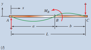
| M_{B}=\text { concentrated moment at } B Between A and B : y=\frac{-M_{B}}{6 E I}\left[\left(6 a-\frac{3 a^{2}}{L}-2 L\right) x-\frac{x^{3}}{L}\right] Between B and C : y=\frac{M_{B}}{6 E I}\left[3 a^{2}+3 x^{2}-\frac{x^{3}}{L}-\left(2 L+\frac{3 a^{2}}{L}\right) x\right] |
 |
| At C at end of overhang: y_{C}=\frac{-P a^{2}}{3 E l}(L+a) At D, maximum upward deflection: y_{D}=0.06415 \frac{P a L^{2}}{E l} |
 |
| At C at center: y=\frac{-W L-2 a)^{3}}{384 E l}\left[\frac{5}{L}(L-2 a)-\frac{24}{L}\left(\frac{a^{2}}{L-2 a}\right)\right] At A and E at ends: y=\frac{-W L-2 a)^{3} a}{24 E I L}\left[-1+6\left(\frac{a}{L-2 a}\right)^{2}+3\left(\frac{a}{L-2 a}\right)^{3}\right] |
 |
| At C at center: y=\frac{P L^{2} a}{8 E I} At A and E at ends at loads: y=\frac{-P a^{2}}{3 E I}\left(a+\frac{3}{2} L\right) |
 |
| At B : y=0.03208 \frac{w a^{2} L^{2}}{E l} At D at end: y=\frac{-w a^{3}}{24 E l}(4 L+3 a) |
 |
y=F L^{3} / 48 E I
In this design,
\begin{aligned}&F=310 \mathrm{lb}=\text { maximum load on the bar } \\&L=24.0 \mathrm{in}=\text { distance between supports } \\&E=30 \times 10^{6} \mathrm{psi}=\text { modulusof elasticity of steel } \\&I=t h^{3} / 12=\text { moment of inertia of the cross section }\\&I=(0.50 \mathrm{in})(2.00 \mathrm{in})^{3} / 12=0.333 \mathrm{in}^{4}\end{aligned}
Then,
y=\frac{(310 \mathrm{lb})(24.0 \mathrm{in})^{3}}{48\left(30 \times 10^{6} \mathrm{lb} / \mathrm{in}^{2}\right)\left(0.333 \mathrm{in}^{4}\right)}=0.0089 \mathrm{in}
This value seems satisfactory. In Section 5-11, some guidelines were given for deflection of machine elements. One stated that bending deflections for general machine parts should be limited to the range of 0.0005 to 0.003 in/in of beam length. For the bar in this design, the ratio of y /L can be compared to this range:
y /L = (0.0089 in)/(24.0 in) = 0.0004 in/in of beam length
Therefore, this deflection is well within the recommended range.
b. Buckling of the bar: When a beam with a tall, thin, rectangular cross section is subjected to bending, it would be possible for the shape to distort due to buckling before the bending stresses would cause failure of the material. This is called elastic instability, and a complete discussion is beyond the scope of this book. However, Reference 14 shows a method of computing the critical buckling load for this kind of loading. The pertinent geometrical feature is the ratio of the thickness t of the bar to its height h. It can be shown that the bar as designed will not buckle.
c. Bearing stress on the inside surfaces of the holes in the beam: Pins transfer loads between the bar and the mating elements in the conveyor system. It is possible that the bearing stress at the pin–hole interface could be large, leading to excessive deformation or wear. Reference 4 in Chapter 3 indicates that the allowable bearing stress for a steel pin in a steel hole is 0.90s_y.
\sigma_{b d}=0.90 \mathrm{~s}_{y}=0.90(30000 \mathrm{psi})=27000 \mathrm{psi}
The actual bearing stress at the center hole is found using the projected area, D_{p} t.
\sigma_{b}=F / D_{p} t=(310 \mathrm{lb}) /(0.50 \mathrm{in})(0.50 \mathrm{in})=1240 \mathrm{psi}
Thus the pin and hole are very safe for bearing.


