(a) The axial pitch is the same as the transverse circular pitch of the gear, which is
p_{x} = p_{t} =\frac{π}{P} =\frac{π}{6} = 0.5236 in
The pitch diameter of the gear is d_{G} = N_{G}/P = 30/6 = 5 in. Therefore, the center distance is
C =\frac{d_{W} + d_{G}}{2} =\frac{2 + 5}{2} = 3.5 in
From Eq. (13–27), the lead is
L = p_{x} N_{W} (13–27)
L = p_{x} N_{W} = (0.5236)(2) = 1.0472 in
Also using Eq. (13–28), find
tan λ =\frac{L}{πd_{W}} (13–28)
λ = tan^{−1} \frac{ L}{πd_{W}} = tan^{−1} \frac{1.0472}{π(2)} = 9.46°
(b) Using the right-hand rule for the rotation of the worm, you will see that your thumb points in the positive z direction. Now use the bolt-and-nut analogy (the worm is righthanded, as is the screw thread of a bolt), and turn the bolt clockwise with the right hand while preventing nut rotation with the left. The nut will move axially along the bolt toward your right hand. Therefore the surface of the gear (Fig. 13–43) in contact with the worm will move in the negative z direction. Thus, the gear rotates clockwise about x, with your right thumb pointing in the negative x direction.
The pitch-line velocity of the worm is
V_{W} =\frac{πd_{W}n_{W}}{12} =\frac{π(2)(1200)}{12} = 628 ft/min
The speed of the gear is n_{G} = ( \frac{2}{30} )(1200) = 80 rev/min. Therefore the pitch-line velocity of the gear is
V_{G} =\frac{πd_{G}n_{G}}{12} =\frac{π(5)(80)}{12} = 105 ft/min
Then, from Eq. (13–47), the sliding velocity VS is found to be
V_{S} =\frac{V_{W}}{cos λ} (13–47)
V_{S} =\frac{V_{W}}{cos λ} =\frac{628}{cos 9.46°} = 637 ft/min
Getting to the forces now, we begin with the horsepower formula
W_{Wt} =\frac{33 000H}{V_{W}} =\frac{(33 000)(1)}{628} = 52.5 lbf
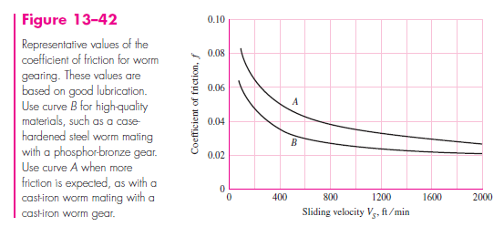
This force acts in the negative x direction, the same as in Fig. 13–40. Using Fig. 13–42, we find f = 0.03. Then, the first equation of group (13–42) and (13–43) gives
W_{Wt} = −W_{Ga} = W^{x}
W_{Wr} = −W_{Gr} = W^{y}
W_{Wa} = −W_{Gt} = W^{z} (13–42)
W^{x} = W (cos \phi _{n} sin λ + f cos λ)
W^{y} = W sin \phi _{n}
W^{z} = W (cos \phi _{n} cos λ − f sin λ) (13–43)
W =\frac{W^{x}}{cos \phi_{n} sin λ + f cos λ}
=\frac{52.5}{cos 14.5° sin 9.46° + 0.03 cos 9.46°} = 278 lbf
Also, from Eq. (13–43),
W^{y} = W sin \phi _{n} = 278 sin 14.5° = 69.6 lbf
W^{z} = W (cos \phi _{n} cos λ − f sin λ)
= 278(cos 14.5° cos 9.46° − 0.03 sin 9.46°) = 264 lbf
We now identify the components acting on the gear as
W_{Ga} = −W^{x} = 52.5 lbf
W_{Gr} = −W^{y} = −69.6 lbf
W_{Gt} = −W^{z} = −264 lbf
At this point a three-dimensional line drawing should be made in order to simplify the work to follow. An isometric sketch, such as the one of Fig. 13–44, is easy to make and will help you to avoid errors.
We shall make B a thrust bearing in order to place the gearshaft in compression. Thus, summing forces in the x direction gives
F^{x}_{B} = −52.5 lbf
Taking moments about the z axis, we have
−(52.5)(2.5) − (69.6)(1.5) + 4F^{y}_{B} = 0 F^{y}_{B} = 58.9 lbf
Taking moments about the y axis,
(264)(1.5) − 4F^{z}_{B} = 0 F^{z}_{B} = 99 lbf
These three components are now inserted on the sketch as shown at B in Fig. 13–44. Summing forces in the y direction,
−69.6 + 58.9 + F^{y}_{A} = 0 F^{y}_{A} = 10.7 lbf
Similarly, summing forces in the z direction,
−264 + 99 + F^{z}_{A} = 0 F^{z}{A} = 165 lbf
These two components can now be placed at A on the sketch. We still have one more equation to write. Summing moments about x,
−(264)(2.5) + T = 0 T = 660 lbf · in
It is because of the frictional loss that this output torque is less than the product of the gear ratio and the input torque.