Question 7.12: Determine the horizontal deflection at joint C of the frame ...
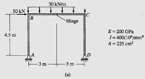
Determine the horizontal deflection at joint C of the frame shown in Fig. 7.17(a) including the effect of axial deformations, by the virtual work method.
Learn more on how we answer questions.
The real and virtual systems are shown in Fig. 7.17(b) and (c), respectively. The x coordinates used for determining the bending moment equations for the three members of the frame, AB, BC, and CD, are also shown in the figures. The equations for M and M_v obtained for the three members are tabulated in Table 7.10 along with the axial forces F and F_v of the members. The horizontal deflection at joint C of the frame can be determined by applying the virtual work expression given by Eq. (7.35):
1(Δ) =∑F_v (\frac{FL}{AE}) + ∑∫\frac{M_vM}{EI} dx (7.35)
1(Δ_C) =∑F_v (\frac{FL}{AE}) + ∑∫\frac{M_vM}{EI} dx1(Δ_C) = \frac{1}{AE} [\frac{3}{4}(-52.5)(4.5) + \frac{1}{2}(55)(6) -\frac{3}{4} (-127.5)(4.5)]
+ \frac{1}{EI}[\int_{0}^{4.5}{\frac{x}{2}(-5x) dx}
+ \int_{0}^{6}{(7.5 – \frac{3}{4}x) (-22.5 + 52.5x – x^2)dx} + \int_{0}^{4.5}{\frac{x}{2}(55x) dx}]
(1 k)Δ_C = \frac{418.125 kN^2-m}{AE} + \frac{3246.75 kN^2-m}{EI}
| TABLE 7.10 | ||||||
| Segment | x Coordinate | M (kN-m) | F (kN) | M_v (kN-m) | F_v (kN) | |
| Origin | Limits (m) | |||||
| AB | A | 0-4.5 | -5x | -52.5 | \frac{x}{2} | \frac{3}{4} |
| BC | B | 0-6 | -22.5 + 52.5x – x² | -55 | 7.5 –\frac{3}{4}x | \frac{1}{2} |
| DC | D | 0-4.5 | 55x | -127.5 | \frac{x}{2} | -\frac{3}{4} |
Therefore,
Δ_C = \frac{418.125 kN^2-m}{AE} + \frac{3246.75 kN^2-m}{EI}= \frac{418.125 }{225(10^{-4})200(10^6)} + \frac{3246.75 }{200(10^6)400(10^{-6})}
= 0.000093 + 0.040584
= 0.04068 m
Δ_C = 40.68 mm. →
Note that the magnitude of the axial deformation term is negligibly small as compared to that of the bending deformation term.

