Question 5.5: Determine the cumulative damage experienced by a ground circ...

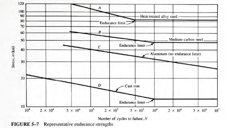
Determine the cumulative damage experienced by a ground circular rod, 1.50 in diameter, subjected to the combination of the cycles of loading and varying levels of reversed, repeated bending stress shown in Table 5-3. The bar is made from AISI 6150 OQT1100 alloy steel. The σ-N curve for the steel is shown in Figure 5-7, curve A for the standard, polished R. R. Moore type specimen.

TABLE 5-3 Loading pattem for Example Problem 5-5
Stress level
(ksi)
Cycles
n_i
80 4000
70 6000
65 10000
60 25000
55 15000
45 1500
The Blue Check Mark means that this solution has been answered and checked by an expert. This guarantees that the final answer is accurate.
Learn more on how we answer questions.

Given       AISI 6150 OQT 1100 alloy steel rod. D = 1.50 in. Ground surface.
Endurance strength data (σ-N) .shown in Figure 5-7, curve A.
Loading is reversed, repeated bending. Load history shown in Table 5-3.
Analysis     First adjust σ-N data for actual conditions using methods of Section 5 -4 . Use Miner’s rule to estimate portion of life used by loading pattern.

Results For AISI 6150 OQT 1100,s_u = 162 ksi (Appendix A4-6) From Figure 5-8, basic s_n= 74 ksi for ground surface Material factor. C_m = 1.00 for wrought steel
Type-of-stress factor, C_{st} = 1.0 for reversed, rotating bending stress Reliability factor. C_{R} = 0.81 (Table 5-1) for R = 0.99 (Design decision) Size factor, C_{s} = 0.84 (Figure 5-9 and Table 5-2 for D = 1.50 in) Estimated actual endurance strength, s′_n Computed:

TABLE 5-2 Size factors
U.S. customary units
Size Range For D in inches
D ≤ 0.30 C_s = 1.0
0.30 < D ≤ 2.0 C_s = (D/0.3)^{-0.11}
2.0< D< 10.0  C_s = 0.859-0,02125D
SI units
Size Range For D in mm
D ≤ 7.62 C_s = 1.0
7.62 < D≤ 50  C_s = (D/7.62)^{-0.11}
50 < D < 250   C_s=0,859-0.000837D
s′_n= s_nC_mC_{st}C_RC_S= (74 \ ksi)(1.0)(1.0)(0.81)(0.84) = 50.3 \ ksi

This is the estimate for the endurance limit ofthe steel. In Figure 5-7, the endurance limit for the standard specimen is 82 ksi. The ratio ofthe actual to the standard data is, 50.3/82 = 0.61.
We can now adjust the entire σ-N curve by this factor. The result is shown in Figure 5-24.

Now we can read the number of cycles of life, N_i, corresponding to each ofthe given loading levels from Table 5-3. The combined data for the number of applied load cycles, n_i , and the life cycles, N_i, are now u.sed in Miner’s rule. Equation 5-31, to determine the cumulative damage, D_c

D_c =\sum\limits_{i=1}^{i=k}{(n_i/N_i)}                  (5-31)

Stress level
(ksi)
Cycles n_i Life cycles
N_i
n_i/N_i
80 4000 2.80 × 10^4 0.143
70 6000 6.60 ×10^4 0.0909
65 10000 1.05 ×10^5 0.0952
60 25000 1.70 ×10^5 0.147
55 15000 2.85 ×10^5 0.0526
45 1500 \infty 0
Total:
0.529

Comment    We can conclude from this number that approximately 53% of the life of the component has been accumulated by the given loading. For these data, the greatest damage occurs from the 60 ksi loading for 25 000 cycles. An almost equal amount of damage is cau.sed by the 80 ksi loading for only 4000 cycles. Note that the cycles of loading at 45 ksi contributed
nothing to the damage because they are below the endurance limit of the steel.

5.24

Related Answered Questions