Question 8.1: Two forces P1 and P2, of magnitude P1 = 15 kN and P2 = 18 kN...
Two forces P_1 and P_2, of magnitude P_1 = 15 kN and P_2 = 18 kN, are applied as shown to the end A of bar AB, which is welded to a cylindrical member BD of radius c = 20 mm (Fig. 8.21). Knowing that the distance from A to the axis of member BD is a= 50 mm and assuming that all stresses remain below the proportional limit of the material, determine (a) the normal and shearing stresses at point K of the transverse section of member BD located at a distance b = 60 mm from end B, (b) the principal axes and principal stresses at K, (c) the maximum shearing stress at K.

Learn more on how we answer questions.
Internal Forces in Given Section. We first replace the forces P_1 and P_2 by an equivalent system of forces and couples applied at the center C of the section containing point K (Fig. 8.22). This system, which represents the internal forces in the section, consists of the following forces and couples:
1. A centric axial force F equal to the force P_1, of magnitude
F = P_1 = 15 kN
2. A shearing force V equal to the force P_2, of magnitude
V = P_2 = 18 kN
3. A twisting couple T of torque T equal to the moment of P_2 about the axis of member BD:
T=P_{2} a=(18 kN )(50 mm )=900 N \cdot m
4. A bending couple M _{y}, of moment M _{y} equal to the moment of P_1 about a vertical axis through C:
M_{y}=P_{1} a=(15 kN )(50 mm )=750 N \cdot m
5. A bending couple M _{z}, of moment M _{z} equal to the moment of P_2 about a transverse, horizontal axis through C:
M_{z}=P_{2} b=(18 kN )(60 mm )=1080 N \cdot mThe results obtained are shown in Fig. 8.23.
a. Normal and Shearing Stresses at Point K. Each of the forces and couples shown in Fig. 8.23 can produce a normal or shearing stress at point K. Our purpose is to compute separately each of these stresses, and then to add the normal stresses and add the shearing stresses. But we must first determine the geometric properties of the section.
Geometric Properties of the Section. We have
A= p c^{2}= p (0.020 m )^{2}=1.257 \times 10^{-3} m ^{2}I_{y}=I_{z}=\frac{1}{4} p c^{4}=\frac{1}{4} p (0.020 m )^{4}=125.7 \times 10^{-9} m ^{4}
J_{C}=\frac{1}{2} p c^{4}=\frac{1}{2} p (0.020 m )^{4}=251.3 \times 10^{-9} m ^{4}
We also determine the first moment Q and the width t of the area of the cross section located above the z axis. Recalling that \bar{y}=4 c / 3 p for a semicircle of radius c, we have
Q=A^{\prime} \bar{y}=\left(\frac{1}{2} p c^{2}\right)\left(\frac{4 c}{3 p }\right)=\frac{2}{3} c^{3}=\frac{2}{3}(0.020 m )^{3}=5.33 \times 10^{-6} m ^{3}
and
t = 2c = 2(0.020 m) = 0.040 m
Normal Stresses. We observe that normal stresses are produced at K by the centric force F and the bending couple M _{y}, but that the couple M _{z} does not produce any stress at K, since K is located on the neutral axis corresponding to that couple. Determining each sign from Fig. 8.23, we write
s _{x}=-\frac{F}{A}+\frac{M_{y} c}{I_{v}}=-11.9 MPa +\frac{(750 N \cdot m )(0.020 m )}{125.7 \times 10^{-9} m ^{4}}
= -11.9 MPa + 119.3 MPa
s_{x} = +107.4 MPa
Shearing Stresses. These consist of the shearing stress \left( t_{x y}\right)_{V} due to the vertical shear V and of the shearing stress \left( t _{x y}\right)_{\text {twist }} caused by the torque T. Recalling the values obtained for Q, t, I_{z}, and J_{C}, we write
\left( t _{x y}\right)_{V}=+\frac{V Q}{I_{z} t}=+\frac{\left(18 \times 10^{3} N \right)\left(5.33 \times 10^{-6} m ^{3}\right)}{\left(125.7 \times 10^{-9} m ^{4}\right)(0.040 m )}
= +19.1 MPa
\left( t _{x y}\right)_{\text {twist }}=-\frac{T c}{J_{C}}=-\frac{(900 N \cdot m )(0.020 m )}{251.3 \times 10^{-9} m ^{4}}=-71.6 MPa
Adding these two expressions, we obtain t _{x y} at point K.
t _{x y}=\left( t _{x y}\right)_{V}+\left( t _{x y}\right)_{\text {twist }}=+19.1 MPa -71.6 MPat _{x y}=-52.5 MPa
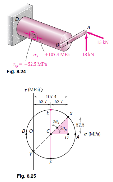
In Fig. 8.24, the normal stress s_{x} and the shearing stresses and t _{x y} have been shown acting on a square element located at K on the surface of the cylindrical member. Note that shearing stresses acting on the longitudinal sides of the element have been included.
b. Principal Planes and Principal Stresses at Point K. We can use either of the two methods of Chap. 7 to determine the principal planes and principal stresses at K. Selecting Mohr’s circle, we plot point X of coordinates s _{x}=+107.4 MPa and – t _{x y}=+52.5 MPa and point Y of coordinates s_{y}=0 and + t _{x y}=-52.5 MPa and draw the circle of diameter XY (Fig. 8.25). Observing that
O C=C D=\frac{1}{2}(107.4)=53.7 MPa DX = 52.5 MPa
we determine the orientation of the principal planes:
\tan 2 u _{p}=\frac{D X}{C D}=\frac{52.5}{53.7}=0.97765 2 u _{p}=44.4^{\circ} i
u _{p}=22.2^{\circ} i
We now determine the radius of the circle,
R=\sqrt{(53.7)^{2}+(52.5)^{2}}=75.1 MPa
and the principal stresses,
s _{\max }=O C+R=53.7+75.1=128.8 MPas _{\min }=O C-R=53.7-75.1=-21.4 MPa
The results obtained are shown in Fig. 8.26.
c. Maximum Shearing Stress at Point K. This stress corresponds to points E and F in Fig. 8.25. We have
t _{\max }=C E=R=75.1 MPaObserving that 2 u _{s}=90^{\circ}-2 u _{p}=90^{\circ}-44.4^{\circ}=45.6^{\circ}, we conclude that the planes of maximum shearing stress form an angle u_{p}=22.8^{\circ}\curvearrowleft with the horizontal. The corresponding element is shown in Fig. 8.27. Note that the normal stresses acting on this element are represented by OC in Fig. 8.25 and are thus equal to +53.7 MPa.