A gear pair is to be designed to transmit 15.0 kilowatts (kW) of power to a large meat grinder in a commercial meat processing plant. The pinion is attached to the shaft of an electric motor rotating at 575 rpm. The gear must operate at 270 to 280 rpm. The gear unit will be enclosed and of commercial quality. Commercially bobbed (quality number 5), 20°, full depth, involute gears are to be used in the metric module system. The maximum center distance
is to be 200 mm. Specify the design of the gears. Use K_p = C_H = SF = Z_N = 1.00.
Share
Share
Question 9.6: A gear pair is to be designed to transmit 15.0 kilowatts (kW...
The Blue Check Mark means that this solution has been answered and checked by an expert. This guarantees that the final answer is accurate.
Learn more on how we answer questions.
Learn more on how we answer questions.
The nominal velocity ratio is
VR = 575/275 = 2.09
Specify an overload factor of K_o = 1.50 from Table 9-5 for a uniform power source and moderate shock for the meat grinder. Then computer design power,
| TABLE 9-5 Suggested overload factors, K_o | ||||
| Driven Machine |
||||
| Power source | Uniform | Light shock |
Moderate shock |
Heavy shock |
| Uniform | 1 | 1.25 | 1.5 | 1.75 |
| Light shock | 1.2 | 1.4 | 1.75 | 2.25 |
| Moderate shock | 1.3 | 1.7 | 2 | 2.75 |
P_{des} = K_oP = (1.50)( 15 \ kW) = 22.5 kW
From Figure 9-27, m= 4 is a reasonable trial module. Then
N_p = 18 (design decision)
D_p = N_pm = (18)(4) = 72 mm
N_G = N_p(VR) = (18)(2.09) = 37.6 (Use 38.)
D_G = N_Gm = (38)(4) = 152 mm
Final output speed = n_G = n_p(N_p/N_G)
n_G = 575 rpm × (18/38) = 272 rpm (okay)
Center distance = C=(N_p/N_G)m/2 [Equation (8-18)]
C=\frac{1}{2} \left[\frac{N_G}{P_d} +\frac{N_P}{P_d} \right] =\frac{(N_G + N_p)}{2P_d} (8-18)
C = (18 + 38)(4)/2 = 112 mm (okay)
In SI units, the pitch line speed in meters per second (m/s) is
V_t = πD_pn_p/(60 000)
where D_p is in mm and n_p is in revolutions per minute (rpm). Then
V_t = [(π)(72)(575)]/(60000) = 2.17 m/s
In SI units, the transmitted load, W_t is in newtons (N). If the power, P, is in kW and v_t is in m/s,
W_t= 1000(P)/v_t = (1000)(15)/(2.17) = 6920 N
In the U.S. Customary Unit System, it was recommended that the face width be approximately F = 12/P_d in. The equivalent SI value is F = 12(m) mm. For this problem, F = 12(4) = 48 mm. Let’s use F = 50 mm.
Other factors are found as before.
K_s= K_B= 1.00
K_v = 1.34 (Figure 9-21)
K_m= 1.21 (Figures 9-19 and 9-19) (F/D_p = 50/72 = 0.69)
J_P = 0.315 J_G = 0.380 [Figure 9-17(a)]
Then the stress in the pinion is found from Equation (9-15), modified by letting P_d = 1/m:
S_t=\frac{W_tP_d}{FJ}K_oK_sK_mK_BK_v
S_{tp}=\frac{W_tK_oK_sK_BK_mK_v}{FmJ_p}=\frac{(6920)(1.50)(1)(1.21)(1.34)}{(50)(4)(0.315)} =269MPa
This is a reasonable stress level. The required hardness of grade 1 material is HB 360, as found in Figure 9-10. Proceed with design for pitting resistance. For two steel gears,
K_s = 1.0
C_P = 191 (Table 9-10)
I = 0.092 (Figure 9-23)
K_v = 1.34
K_o = 1.50
K_m= 1.21
| TABLE 9-10 Recommended lubricant grade for spur, helical, herringbone, and bevel gear drives. | ||||
| Ambient temperature | ||||
| Pitch line velocity | -40° to 14° F -40° C to -10° C |
14°F to50°F -10° C to 10° C |
50°F to 95°F 1010° C to 35°C |
93° F to 131°F 33°C to 55°C |
| Lubricant grade | ||||
| Less than 1000 ft/min Less than 5 m/s |
3S | 4 | 6 | 8 |
| 1000 to 3000 ft/min 5 to 15 m/s |
3S | 3 | 5 | 7 |
| 3000 to 3000 ft/min 13 to 25 m/s |
2S | 2 | 4 | 6 |
| Over 3000 ft/min Over 23 m/s |
0S | 0 | 2 | 3 |
| Extracted from AGMA Standard 9005-D94. Industrial Gear Lubrication. with permission of the publisher. American Gear Manufactures Association. 1500 King Street. Suite 201. Alexandria, VA 22314. |
||||
The contact stress [Equation (9-25)] gives
S_{c}=C_P\sqrt{\frac{W_tK_oK_sK_BK_mK_v}{FD_pI}}
S_{c}=C_P\sqrt{\frac{W_tK_oK_sK_BK_mK_v}{FD_pI}}=191\sqrt{\frac{(6920)(1.50)(1.0)(1.21)(1.34)}{(50)(72)(0.092)} }=1367 MPa
Converting to ksi gives
s_c = 1367 MPa × 1 ksi/6.895 MPa = 198 ksi
From Table 9-3, the required surface hardness is HRC 58-64, case-carburized. Grade 2. Material selection from Appendix 5, for carburized steels, is as follows:
| TABLE 9-3 Allowable stress numbers for case-hardened steel gear materials | ||||||
| Allowable bending stress number, s_{ac}(ksi) |
Allowable contact stress number, s_{ac} (ksi) |
|||||
| Hardness at surface |
Grade 1 | Grade 2 | Grade 3 | Grade 1 | Grade 2 | Grade 3 |
| Flame- or induction-hardened: | ||||||
| 50 HRC | 45 | 55 | 170 | 190 | ||
| 54 HRC | 45 | 55 | 175 | 195 | ||
| Carburized and case-hardened | ||||||
| 55-64 HRC | 55 | 180 | ||||
| 58-64 HRC | 55 | 65 | 75 | 180 | 225 | 275 |
| Nitrided, through-hardened steels: | ||||||
| 83.5 HR 15N | See Figure 9-14. | 150 | 163 | 175 | ||
| 84.5 HR 15N | See Figure 9-14. | 155 | 168 | 180 | ||
| Nitrided. nitralloy 135 M^a | ||||||
| 87.5 HR 15N | See Figure 9-15. | |||||
| 90.0 HR 15N | See Figure 9-15. | 170 | 183 | 195 | ||
| Nitrided, nitralloy N^a: | ||||||
| 87.5 HR 15N | See Figure 9-15. | |||||
| 90.0 HR 15N | See Figure 9-15. | 172 | 188 | 205 | ||
| Nitrided. 2.5% chrome (no aluminum): | ||||||
| 87.5 HR 15N | See Figure 9-15. | 155 | 172 | 189 | ||
| 90.0 HR 15N | See Figure 9-15. | 176 | 196 | 216 | ||
| Source: Extracted from AGMA Standard 2001 -C95. Fundamental Rating Factors and Calculation Methods for Involute Spur and Helical Gear Teeth, with the permission of the publisher. American Gear Manufacturers Association, 1500 King Street. Suite 201. Alexandria. VA 22314. Nitralloy is a proprietary family of steels containing approximately 1 .0% aluminum which enhances the formation of hard nitrides |
||||||
AISI 4320 SOQT 300; s_a = 1500 MPa ; 13% elongation. Grade 2
Case-harden by carburizing to HRC 58 minimum
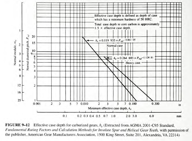
Case depth: 0.6 mm minimum (Figure 9-12)
Comment: Redesigning the gears to permit using Grade 1 material is recommended


Related Answered Questions
General Design Procedure
Step 1. Considering the t...
In Example Problem 9-3, we found that the expected...
The results of Example Problem 9-1 include the exp...
Data from Example Problem 9_1 are summarized as f...
We will use Equation (9_15) to compute the expecte...