Design the plates for the column specified in Example 11.2. Take the minimum feed rate as 70 per cent of the maximum (maximum feed 10,000 kg/h). Use sieve plates.
Question 11.11: Design the plates for the column specified in Example 11.2. ...
The Blue Check Mark means that this solution has been answered and checked by an expert. This guarantees that the final answer is accurate.
Learn more on how we answer questions.
Learn more on how we answer questions.
As the liquid and vapour flow-rates and compositions will vary up the column, plate designs should be made above and below the feed point. Only the bottom plate will be designed in detail in this example.
From McCabe-Thiele diagram, Example 11.2:
Number of stages = 16
Slope of the bottom operating line = 5.0
Slope of top operating line = 0.57
Top composition 94 per cent mol. 98 per cent w/w.
Bottom \text { composition – essentially } water.
Reflux ratio = 1.35
Flow-rates
Mol. weight feed = 0.033 x 58 + (1 – 0.033)18 = 19.32
Feed = 13,000/19.32 = 672.9 kmol/h
A mass balance on acetone gives:
Top product, D = 672.9 x 0.033/0.94 = 23.6 kmol/h
Vapour rate, V = D(1 + R) = 23.6(1 + 1.35) = 55.5 kmol/h
An overall mass balance gives:
Bottom product, B = 672.9 – 23.6 = 649.3 kmol/h
Slope of the bottom operating line L_{m}^{\prime} / V_{m}^{\prime} = 5.0 and V_{m}^{\prime}=L_{m}^{\prime}- B, from which:
vapour flow below feed, V_{m}{ }^{\prime} = 162.3 kmol/h
liquid flow below feed, L_{m}{ }^{\prime} = 811.6 kmol/h
Physical properties
Estimate base pressure, assume column efficiency of 60 per cent, take reboiler as equivalent to one stage.
\text { Number of real stages }=\frac{16-1}{0.6}=25
Assume 100 mm water, pressure drop per plate.
\text { Column pressure drop }=100 \times 10^{-3} \times 1000 \times 9.81 \times 25=24,525 Pa
\text { Top pressure, } 1 atm \left(14.7 lb / in ^{2}\right)=101.4 \times 10^{3} Pa
\text { Estimated bottom pressure }=101.4 \times 10^{3}+24,525 = 125,925 Pa = 1.26 bar
From steam tables, base temperature 106^{\circ} C.
\rho_{v}=0.72 kg / m ^{3}
\rho_{L}=954 kg / m ^{3}
\text { Surface tension } 57 \times 10^{-3} N / m
Top, 98% w/w acetone, top temperature 57^{\circ} C
From PPDS (see Chapter 8);
\rho_{v}=2.05 kg / m ^{3}, \rho_{L}=753 kg / m ^{3}
Molecular weight 55.6
\text { Surface tension } 23 \times 10^{-3} N / m
Column diameter
F_{L V} \text { bottom }=5.0 \sqrt{\frac{0.72}{954}}=0.14 (11.82)
F_{L V} \text { top }=0.57 \sqrt{\frac{2.05}{753}}=0.03
Take plate spacing as 0.5 m
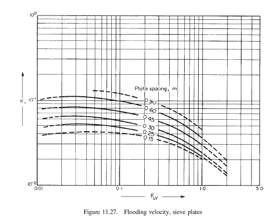
From Figure 11.27
\text { base } K_{1}=7.5 \times 10^{-2}
\operatorname{top} K_{1}=9.0 \times 10^{-2}
Correction for surface tensions
\text { base } K_{1}=\left(\frac{57}{20}\right)^{0.2} \times 7.5 \times 10^{-2}=9.3 \times 10^{-2}
\text { top } K_{1}=\left(\frac{23}{20}\right)^{0.2} \times 9.0 \times 10^{-2}=9.3 \times 10^{-2}
\text { base } u_{f}=9.3 \times 10^{-2} \sqrt{\frac{954-0.72}{0.72}}=3.38 m / s (11.81)
\text { top } u_{f}=9.3 \times 10^{-2} \sqrt{\frac{753-2.05}{2.05}}=1.78 m / s
Design for 85 per cent flooding at maximum flow rate
\text { base } \hat{u_{v}}=3.38 \times 0.85=2.87 m / s
\text { top } \hat{u_{v}}=1.78 \times 0.85=1.51 m / s
Maximum volumetric flow-rate
\text { base }=\frac{162.3 \times 18}{0.72 \times 3600}=1.13 m ^{3} / s
\text { top }=\frac{55.5 \times 55.6}{2.05 \times 3600}=0.42 m ^{3} / s
Net area required
\text { bottom }=\frac{1.13}{2.87}=0.40 m ^{2}
t o p=\frac{0.42}{1.51}=0.28 m ^{2}
As first trial take downcomer area as 12 per cent of total.
Column cross-sectioned area
\text { base }=\frac{0.40}{0.88}=0.46 m ^{2}
\text { top }=\frac{0.28}{0.88}=0.32 m ^{2}
Column diameter
\text { base }=\sqrt{\frac{0.46 \times 4}{\pi}}=0.77 m
\text { top }=\sqrt{\frac{0.34 \times 4}{\pi}}=0.64 m
Use same diameter above and below feed, reducing the perforated area for plates above the feed.
Nearest standard pipe size (BS 1600); outside diameter 812.8 mm (32 in); standard wall thickness 9.52 mm; inside diameter 794 mm.
Liquid flow pattern
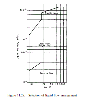
\text { Maximum volumetric liquid rate }=\frac{811.6 \times 18}{3600 \times 954}=4.3 \times 10^{-3} m ^{3} / s
The plate diameter is outside the range of Figure 11.28, but it is clear that a single pass plate can be used.
Provisional plate design
\text { Column diameter } D_{c}=0.79 m
\text { Column area } A_{c}=0.50 m ^{2}
\text { Downcomer area } A_{d}=0.12 \times 0.50=0.06 m ^{2} \text {, at } 12 \text { per cent }
\text { Net area } A_{n}=A_{c}-A_{d}=0.50-0.06=0.44 m ^{2}
\text { Active area } A_{a}=A_{c}-2 A_{d}=0.50-0.12=0.38 m ^{2}
\text { Hole area } A_{h} \text { take } 10 \text { per cent } A_{a} \text { as first trial }=0.038 m ^{2}
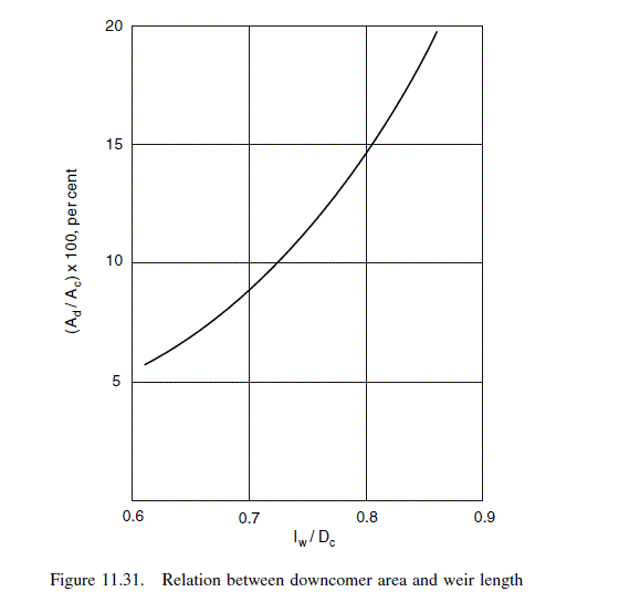
Weir length (from Figure 11.31) = 0.76 x 0.79 = 0.60 m
Take weir height 50 mm
Hole diameter 5 mm
Plate thickness 5 mm
Check weeping
\text { Maximum liquid rate }=\left(\frac{811.6 \times 18}{3600}\right)=4.06 kg / s
Minimum liquid rate, at 70 per cent turn-down = 0.7 x 4.06 = 2.84 kg/s
\text { maximum } h_{o w}=750\left(\frac{4.06}{954 \times 0.06}\right)^{2 / 3}=27 mm \text { liquid } (11.85)
\text { minimum } h_{o w}=750\left(\frac{2.85}{954 \times 0.60}\right)^{2 / 3}=22 mm \text { liquid }
\text { at minimum rate } h_{w}+h_{o w}=50+22=72 mm
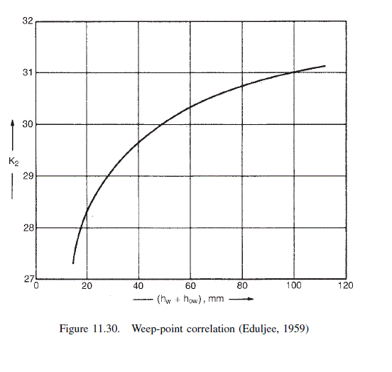
From Figure 11.30,
K_{2}=30.6
\check{u}_{h}(\min )=\frac{30.6-0.90(25.4-5)}{(0.72)^{1 / 2}}=14 m / s (11.84)
\text { actual minimum vapour velocity }=\frac{\text { minimum vapour rate }}{A_{h}} =\frac{0.7 \times 1.13}{0.038}=20.8 m / s
So minimum operating rate will be well above weep point.
Plate pressure drop
Dry plate drop
Maximum vapour velocity through holes
\hat{u}_{h}=\frac{1.13}{0.038}=29.7 m / s
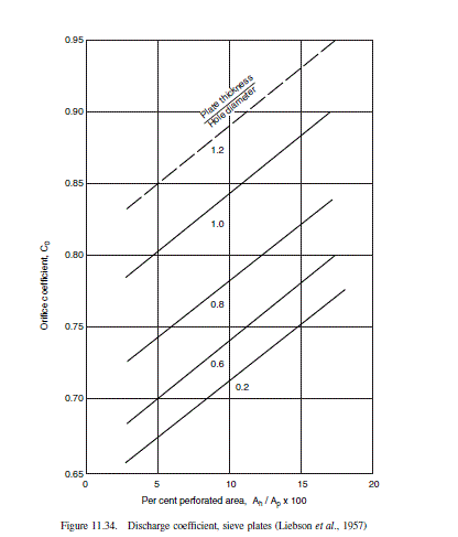
From Figure 11.34, for plate thickness/hole dia.=1, \text { and } A_{h} / A_{p} \simeq A_{h} / A_{a}=0.1 C_{0}=0.84
h_{d}=51\left(\frac{29.7}{0.84}\right)^{2} \frac{0.72}{954}=48 mm \text { liquid } (11.88)
residual head
h_{r}=\frac{12.5 \times 10^{3}}{954}=13.1 mm \text { liquid } (11.89)
total plate pressure drop
h_{t}=48+(50+27)+13=138 mm \text { liquid }
Note: 100 mm was assumed to calculate the base pressure. The calculation could be repeated with a revised estimate but the small change in physical properties will have little effect on the plate design. 138 mm per plate is considered acceptable.
Downcomer liquid back-up
Downcomer pressure loss
\text { Take } h_{a p}=h_{w}-10=40 mm
\text { Area under apron, } A_{a p}=0.60 \times 40 \times 10^{-3}=0.024 m ^{2} \text {. }
\text { As this is less than } A_{d}=0.06 m ^{2} \text { use } A_{a p} \text { in equation } 11.92
h_{d c}=166\left(\frac{4.06}{954 \times 0.024}\right)^{2}=5.2 mm (11.92)
say 6 mm.
Back-up in downcomer
h_{b}=(50+27)+138+6=221 mm (11.91)
0.22 m
0.22<\frac{1}{2} \text { (plate spacing }+\text { weir height) }
so plate spacing is acceptable
Check residence time
t_{r}=\frac{0.06 \times 0.22 \times 954}{406}=3.1 s (11.95)
>3 s, satisfactory.
Check entrainment
u_{v}=\frac{1.13}{0.44}=2.57 m / s
\text { per cent flooding }=\frac{2.57}{3.38}=76
F_{L V}=\underline{\underline{0.14}}, \text { from Figure } 11.29, \Psi=0.018 \text {, well below } 0.1 \text {. }
As the per cent flooding is well below the design figure of 85, the column diameter could be reduced, but this would increase the pressure drop.
Trial layout
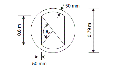
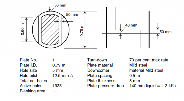
Use cartridge-type construction. Allow 50 mm unperforated strip round plate edge; 50 mm wide calming zones.
Perforated area
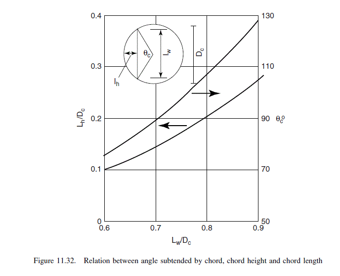
\text { From Figure 11.32, at } l_{w} / D_{c}=0.6 / 0.79=0.76
\theta_{c}=99^{\circ}
\text { angle subtended by the edge of the plate }=180-99=81^{\circ}
\text { mean length, unperforated edge strips }=\left(0.79-50 \times 10^{-3}\right) \pi \times 81 / 180=1.05 m
\text { area of unperforated edge strips }=50 \times 10^{-3} \times 1.05=0.053 m ^{2}
mean length of calming zone, approx. = weir length + width of unperforated strip =0.6+50 \times 10^{-3}=0.65 m
\text { area of calming zones }=2\left(0.65 \times 50 \times 10^{-3}\right)=0.065 m ^{2}
\text { total area for perforations, } A_{p}=0.38-0.053-0.065=0.262 m ^{2}
A_{h} / A_{p}=0.038 / 0.262=0.145
\text { From Figure } 11.33, l_{p} / d_{h}=2.6 \text {; satisfactory, within } 2.5 \text { to } 4.0 \text {. }
Number of holes
\text { Area of one hole }=1.964 \times 10^{-5} m ^{2}
\text { Number of holes }=\frac{0.038}{1.964 \times 10^{-5}}=1935
Plate specification
Related Answered Questions
As the solubility of SO _{2} in wat...
The top and bottom temperatures (dew points and bu...
From Example 11.5, feed composition, mol fractions...
Only sufficient trial calculations will be made to...
Composition of feed + solvent, point o = 0.45 x 10...
Plate will be in the stripping section (see Figure...
From Examples 11.12 and 11.11:
\rho_...
For two phases to exist the flash temperature must...
There is no point in operating this column at othe...
From the McCabe-Thiele diagram in Example 11.2:
sl...