Design an exchanger to sub-cool condensate from a methanol condenser from 95ºC to 40ºC. Flow-rate of methanol 100,000 kg/h. Brackish water will be used as the coolant, with a temperature rise from 25º to 40ºC.
Question 12.1: Design an exchanger to sub-cool condensate from a methanol c...
The Blue Check Mark means that this solution has been answered and checked by an expert. This guarantees that the final answer is accurate.
Learn more on how we answer questions.
Learn more on how we answer questions.
Only the thermal design will be considered.
This example illustrates Kern’s method.
Coolant is corrosive, so assign to tube-side.
\text { Heat capacity methanol }=2.84 kJ / kg ^{\circ} C
\text { Heat load }=\frac{100,000}{3600} \times 2.84(95-40)=4340 kW
\text { Heat capacity water }=4.2 kJ / kg ^{\circ} C
\text { Cooling water flow }=\frac{4340}{4.2(40-25)}=68.9 kg / s
\Delta T_{\operatorname{lm}}=\frac{(95-40)-(40-25)}{\ln \frac{(95-40)}{(40-25)}}=31^{\circ} C (12.4)
Use one shell pass and two tube passes
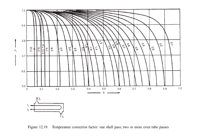
R=\frac{95-40}{40-25}=3.67 (12.6)
S=\frac{40-25}{95-25}=0.21 (12.7)
From Figure 12.19
F_{t}=0.85
\Delta T_{m}=0.85 \times 31=26^{\circ} C
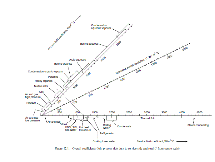
From Figure 12.1
U=600 W / m ^{2}{ }^{\circ} C
Provisional area
A=\frac{4340 \times 10^{3}}{26 \times 600}=278 m ^{2} (12.1)
Choose 20 mm o.d., 16 mm i.d., 4.88-m-long tubes \left(\frac{3}{4} in . \times 16 ft \right), cupro-nickel.
Allowing for tube-sheet thickness, take
L = 4.83 m
\text { Area of one tube }=4.83 \times 20 \times 10^{-3} \pi=0.303 m ^{2}
\text { Number of tubes }=\frac{278}{0.303}=\underline{\underline{918}}
As the shell-side fluid is relatively clean use 1.25 triangular pitch.
\text { Bundle diameter } D_{b}=20\left(\frac{918}{0.249}\right)^{1 / 2.207}=826 mm (12.3b)
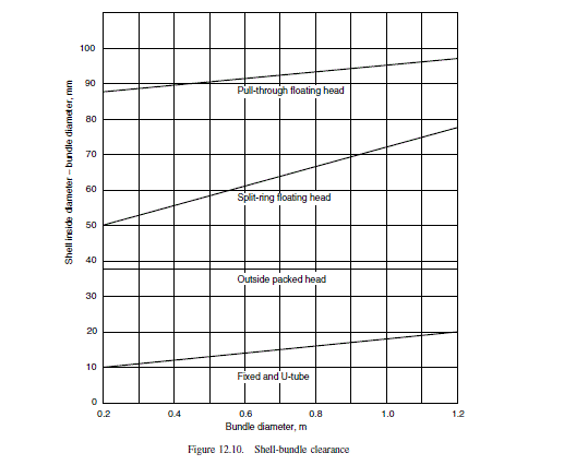
Use a split-ring floating head type.
From Figure 12.10, bundle diametrical clearance = 68 mm,
\text { shell diameter, } D_{s}=826+68=894 mm
(Note. nearest standard pipe sizes are 863.6 or 914.4 mm).
Shell size could be read from standard tube count tables.
Tube-side coefficient
\text { Mean water temperature }=\frac{40+25}{2}=33^{\circ} C
\text { Tube cross-sectional area }=\frac{\pi}{4} \times 16^{2}=201 mm ^{2}
\text { Tubes per pass }=\frac{918}{2}=459
\text { Total flow area }=459 \times 201 \times 10^{-6}=0.092 m ^{2}
\text { Water mass velocity }=\frac{68.9}{0.092}=749 kg / s m ^{2}
\text { Density water }=995 kg / m ^{3}
\text { Water linear velocity }=\frac{749}{995}=0.75 m / s
h_{i}=\frac{4200(1.35+0.02 \times 33) 0.75^{0.8}}{16^{0.2}}=3852 W / m ^{2{ }^{\circ} C } (12.17)
The coefficient can also be calculated using equation 12.15; this is done to illustrate use of this method.
\frac{h_{i} d_{i}}{k_{f}}=j_{h} \operatorname{RePr} r^{0.33}\left(\frac{\mu}{\mu_{w}}\right)^{0.14} (12.15)
\frac{h_{i} d_{i}}{k_{f}}=j_{h} \operatorname{RePr}{ }^{0.33}\left(\frac{\mu}{\mu_{w}}\right)^{0.14}
\text { Viscosity of water }=0.8 mNs / m ^{2}
\text { Thermal conductivity }=0.59 W / m ^{\circ} C
R e=\frac{\rho u d_{i}}{\mu}=\frac{995 \times 0.75 \times 16 \times 10^{-3}}{0.8 \times 10^{-3}}=14,925
\operatorname{Pr}=\frac{C_{p} \mu}{k_{f}}=\frac{4.2 \times 10^{3} \times 0.8 \times 10^{-3}}{0.59}=5.7
\text { Neglect }\left(\frac{\mu}{\mu_{w}}\right)
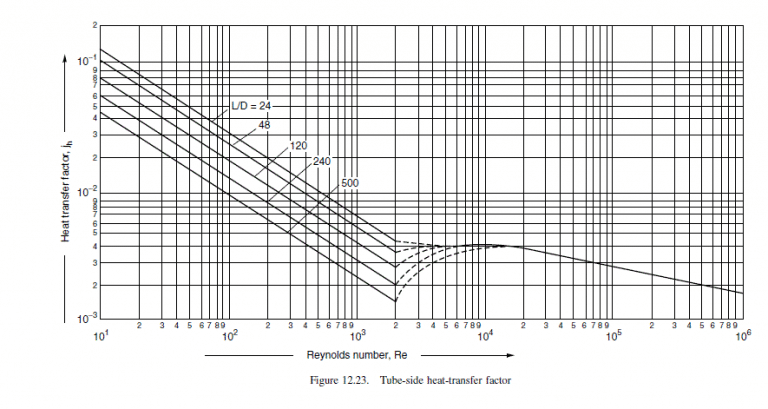
\frac{L}{d_{i}}=\frac{4.83 \times 10^{3}}{16}=302
\text { From Figure } 12.23, j_{h}=3.9 \times 10^{-3}
h_{i}=\frac{0.59}{16 \times 10^{-3}} \times 3.9 \times 10^{-3} \times 14,925 \times 5.7^{0.33}=3812 W / m ^{2{ }^{\circ} C }
Checks reasonably well with value calculated from equation 12.17; use lower figure.
Shell-side coefficient
\text { Choose baffle spacing }=\frac{D_{s}}{5}=\frac{894}{5}=178 mm
\text { Tube pitch }=1.25 \times 20=25 mm
\text { Cross-flow area } A_{s}=\frac{(25-20)}{25} 894 \times 178 \times 10^{-6}=0.032 m ^{2} (12.21)
\text { Mass velocity, } G_{S}=\frac{100,000}{3600} \times \frac{1}{0.032}=868 kg / s m ^{2}
\text { Equivalent diameter } d_{e}=\frac{1.1}{20}\left(25^{2}-0.917 \times 20^{2}\right)=14.4 mm (12.23)
\text { Mean shell side temperature }=\frac{95+40}{2}=68^{\circ} C
\text { Methanol density }=750 kg / m ^{3}
\text { Viscosity }=0.34 mNs / m ^{2}
\text { Heat capacity }=2.84 kJ / kg ^{\circ} C
\text { Thermal conductivity }=0.19 W / m ^{\circ} C
R e=\frac{G_{s} d_{e}}{\mu}=\frac{868 \times 14.4 \times 10^{-3}}{0.34 \times 10^{-3}}=36,762 (12.24)
\operatorname{Pr}=\frac{C_{p} \mu}{k_{f}}=\frac{2.84 \times 10^{3} \times 0.34 \times 10^{-3}}{0.19}=5.1
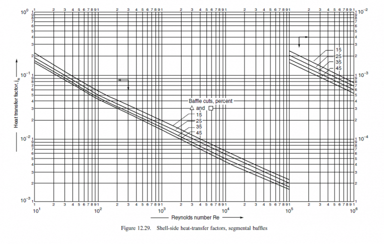
Choose 25 per cent baffle cut, from Figure 12.29
j_{h}=3.3 \times 10^{-3}
Without the viscosity correction term
h_{s}=\frac{0.19}{14.4 \times 10^{-3}} \times 3.3 \times 10^{-3} \times 36,762 \times 5.1^{1 / 3}=2740 W / m ^{2}{ }^{\circ} C
Estimate wall temperature
\text { Mean temperature difference }=68-33=35^{\circ} C
across all resistances
\text { across methanol film }=\frac{U}{h_{o}} \times \Delta T=\frac{600}{2740} \times 35=8^{\circ} C
\text { Mean wall temperature }=68-8=60^{\circ} C
\mu_{w}=0.37 mNs / m ^{2}
\left(\frac{\mu}{\mu_{w}}\right)^{0.14}=0.99
which shows that the correction for a low-viscosity fluid is not significant.
Overall coefficient
Thermal conductivity of cupro-nickel alloys D 50 W / m ^{\circ} C.
Take the fouling coefficients from Table 12.2; methanol (light organic) 5000Wm ^{-2 \circ} C ^{-1},
brackish water (sea water), take as highest value, 3000 Wm ^{-2 \circ} C ^{-1}
| Fluid | \text { Coefficient }\left( W / m ^{2}{ }^{\circ} C \right) | Factor (resistance) (m^2°C/W) |
| River water | 3000-12,000 | 0.0003-0.0001 |
| Sea water | 1000-3000 | 0.001-0.0003 |
| Cooling water (towers) | 3000-6000 | 0.0003-0.00017 |
| Towns water (soft) | 3000-5000 | 0.0003-0.0002 |
| Towns water (hard) | 1000-2000 | 0.001-0.0005 |
| Steam condensate | 1500-5000 | 0.00067-0.0002 |
| Steam (oil free) | 4000-10,000 | 0.0025-0.0001 |
| Steam (oil traces) | 2000-5000 | 0.0005-0.0002 |
| Refrigerated brine | 3000-5000 | 0.0003-0.0002 |
| Air and industrial gases | 5000-10,000 | 0.0002-0.0001 |
| Flue gases | 2000-5000 | 0.0005-0.0002 |
| Organic vapours | 5000 | 0.0002 |
| Organic liquids | 5000 | 0.0002 |
| Light hydrocarbons | 5000 | 0.0002 |
| Heavy hydrocarbons | 2000 | 0.0005 |
| Boiling organics | 2500 | 0.0004 |
| Condensing organics | 5000 | 0.0002 |
| Heat transfer fluids | 5000 | 0.0002 |
| Aqueous salt solutions | 3000-5000 | 0.0003-0.0002 |
\frac{1}{U_{o}}=\frac{1}{2740}+\frac{1}{5000}+\frac{20 \times 10^{-3} \ln \left(\frac{20}{16}\right)}{2 \times 50} +\frac{20}{16} \times \frac{1}{3000}+\frac{20}{16} \times \frac{1}{3812} U_{o}=738 W / m ^{2}{ }^{\circ} C (12.2)
\text { well above assumed value of } 600 W / m ^{2}{ }^{\circ} C \text {. }
Pressure drop
Tube-side
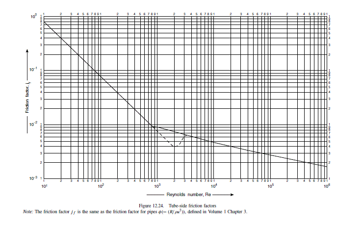
\text { From Figure } 12.24 \text {, for } \operatorname{Re}=14,925
j_{f}=4.3 \times 10^{-3}
Neglecting the viscosity correction term
\Delta P_{t}=2\left(8 \times 4.3 \times 10^{-3}\left(\frac{4.83 \times 10^{3}}{16}\right)+2.5\right) \frac{995 \times 0.75^{2}}{2} =7211 N / m ^{2}=7.2 kPa (1.1 psi ) (12.20)
low, could consider increasing the number of tube passes.
Shell side
\text { Linear velocity }=\frac{G_{s}}{\rho}=\frac{868}{750}=1.16 m / s
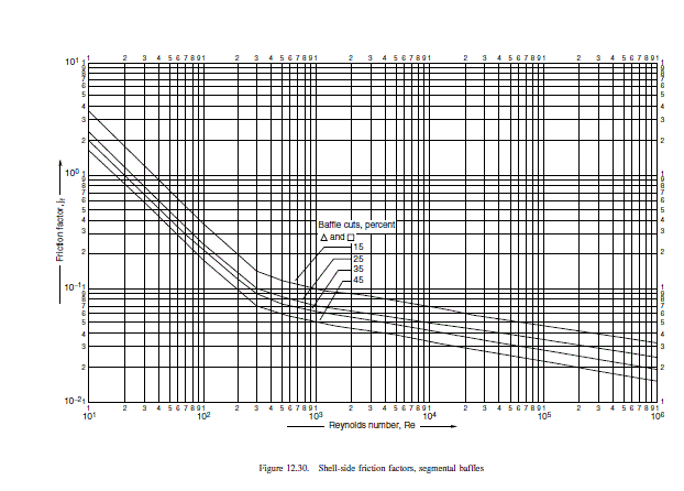
\text { From Figure } 12.30, \text { at } \operatorname{Re}=36,762
j_{f}=4 \times 10^{-2}
Neglect viscosity correction
\Delta P_{s}=8 \times 4 \times 10^{-2}\left(\frac{894}{14.4}\right)\left(\frac{4.83 \times 10^{3}}{178}\right) \frac{750 \times 1.16^{2}}{2} (12.26)
\begin{array}{l}=272,019 N / m ^{2} \\=272 kPa (39 psi ) \text { too high, }\end{array}
could be reduced by increasing the baffle pitch. Doubling the pitch halves the shell-side velocity, which reduces the pressure drop by a factor of approximately (1 / 2)^{2}
\Delta P_{s}=\frac{272}{4}=68 kPa (10 psi ), \text { acceptable }
This will reduce the shell-side heat-transfer coefficient by a factor of (1 / 2)^{0.8}\left(h_{o} \propto\right. \left.R e^{0.8} \propto u_{s}^{0.8}\right)
h_{o}=2740 \times\left(\frac{1}{2}\right)^{0.8}=1573 W / m ^{2}{ }^{\circ} C
This gives an overall coefficient of 615 W / m ^{2}{ }^{\circ} C -\text { still } above assumed value of 600 W / m ^{2}{ }^{\circ} C.
Related Answered Questions
Heat-transfer coefficient
\text { Id...
Physical properties, from steam tables:
[la...
The vapour will flow up and the liquid down the tu...
Physical properties:
\text { boiling...
Physical properties, taken as those of aniline:
Bo...
Only the thermal design will be done. The physical...
Only the thermal design and general layout will be...
\text { The baffle forms a continuous spira...
The concentrations of C _{3} \text { and } ...
\text { Agitator speed }(\text { revs per s...