Heat-transfer coefficient
\text { Ideal bank coefficient, } h_{o c}
A_{s}=\frac{25-20}{25} \times 894 \times 356 \times 10^{-6}=0.062 m ^{2} (12.21)
G_{s}=\frac{100,000}{3600} \times \frac{1}{0.062}=448 kg / s m ^{2}
R e=\frac{G_{s} a_{o}}{\mu}=\frac{440 \times 20 \times 10}{0.34 \times 10^{-3}}=26,353
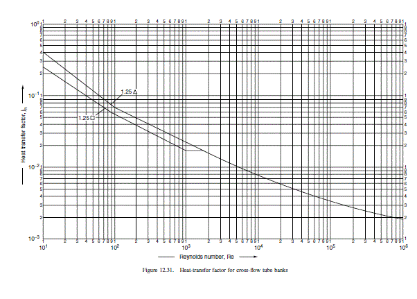
\text { From Figure } 12.31 j_{h}=5.3 \times 10^{-3} \text {. }
Prandtl number, from Example 12.1 = 5.1
\text { Neglect viscosity correction factor }\left(\mu / \mu_{w}\right) \text {. }
h_{o c}=\frac{0.19}{20 \times 10^{-3}} \times 5.3 \times 10^{-3} \times 26,353 \times 5.1^{1 / 3}=2272 W / m ^{2{ }^{\circ} C } (12.20)
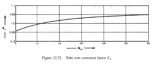
Tube row correction factor, F_{n}
\text { Tube vertical pitch } p_{t}^{\prime}=0.87 \times 25=21.8 mm
\text { Baffle cut height } H_{c}=0.25 \times 894=224 mm
\text { Height between baffle tips }=894-2 \times 224=446 mm
N_{c v}=\frac{446}{21.8}=20
\text { From Figure } 12.32 F_{n}=1.03 \text {. }
\text { Window correction factor, } F_{W}
H_{b}=\frac{826}{2}-894(0.5-0.25)=190 mm (12.38)
“Bundle cut” = 190/826 = 0.23 (23 per cent)
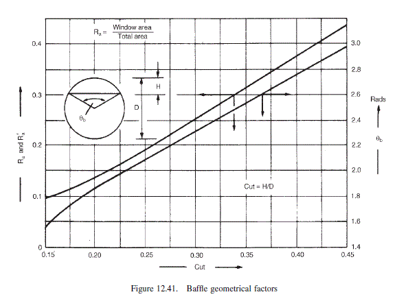
From Figure 12.41 at cut of 0.23
R_{a}^{\prime}=0.18
\text { Tubes in one window area, } N_{w}=918 \times 0.18=165 (12.41)
\text { Tubes in cross-flow area, } N_{c}=918-2 \times 165=588 (12.42)
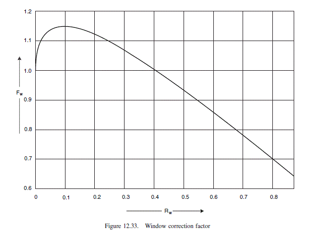
R_{w}=\frac{2 \times 165}{918}=0.36 (12.43)
\text { From Figure } 12.33 F_{w}=1.02 \text {. }
\text { Bypass correction, } F_{b}
A_{b}=(894-826) 356 \times 10^{-6}=0.024 m ^{2} (12.47)
\frac{A_{b}}{A_{s}}=\frac{0.024}{0.062}=0.39
F_{b}=\exp [-1.35 \times 0.39]=0.59 (12.30)
Very low, sealing strips needed; try one strip for each five vertical rows.
\frac{N_{s}}{N_{c v}}=\frac{1}{5}
F_{b}=\exp \left[-1.35 \times 0.39\left(1-\left(\frac{2}{5}\right)^{1 / 3}\right)\right]=0.87 (12.30)
\text { Leakage correction, } F_{L}
Using clearances as specified in the Standards,
\text { tube-to-baffle } \frac{1}{32} \text { in. }=0.8 mm
\text { baffle-to-shell } \frac{3}{16} \text { in. }=4.8 mm
A_{t b}=\frac{0.8}{2} \times 20 \pi(918-165)=18.9 \times 10^{3} mm ^{2}=0.019 m ^{2} (12.45)
\text { From Figure } 12.41,25 \text { per cent cut }(0.25), \theta_{b}=2.1 \text { rads. }
A_{s b}=\frac{4.8}{2} \times 894(2 \pi-2.1)=8.98 \times 10^{3} mm ^{2}=0.009 m ^{2} (12.46)
A_{L}=(0.019+0.009)=0.028 m ^{2}
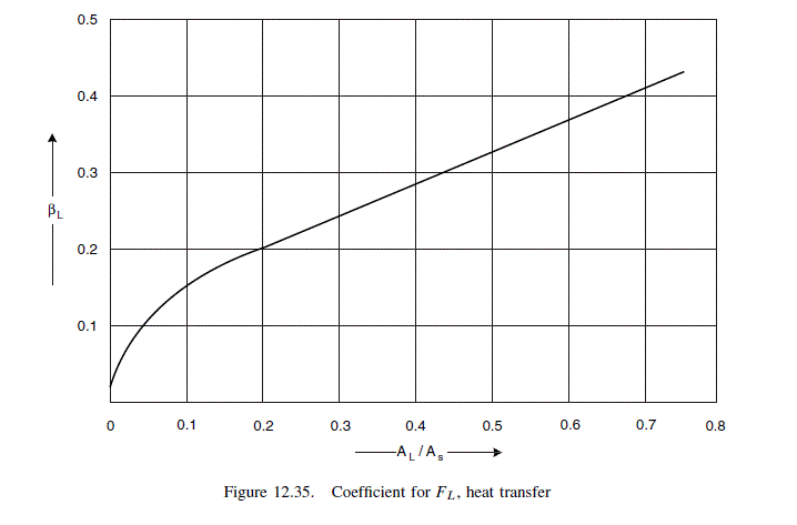
\frac{A_{L}}{A_{s}}=\frac{0.028}{0.062}=0.45
\text { From Figure } 12.35 \beta_{L}=0.3 \text {. }
F_{L}=1-0.3\left[\frac{(0.019+2 \times 0.009)}{0.028}\right]=0.60 (12.31)
Shell-side coefficient
h_{s}=2272 \times 1.03 \times 1.02 \times 0.87 \times 0.60=\underline{\underline{\underline{1246} W / m ^{2}{ }^{\circ} C }} (12.27)
Appreciably lower than that predicted by Kern’s method.
Pressure drop
Cross-flow zone
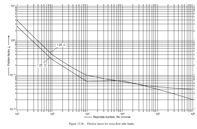
\text { From Figure } 12.36 \text { at } \operatorname{Re}=26,353 \text {, for } 1.25 \Delta \text { pitch, } j_{f}=5.6 \times 10^{-2}
u_{s}=\frac{G_{s}}{\rho}=\frac{448}{750}=0.60 m / s
\text { Neglecting viscosity term }\left(\mu / \mu_{w}\right) \text {. }
\Delta P_{i}=8 \times 5.6 \times 10^{-2} \times 20 \times \frac{750 \times 0.6^{2}}{2}=1209.6 N / m ^{2} (12.33)
(\alpha=4.0) (12.30)
F_{b}^{\prime}=\exp \left[-4.0 \times 0.39\left(1-\left(\frac{2}{5}\right)^{1 / 3}\right)\right]=0.66
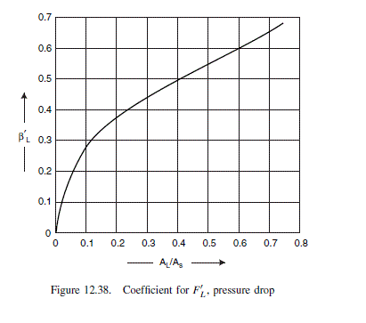
\text { From Figure } 12.38 \beta_{L}^{\prime}=0.52 \text {. }
F_{L}^{\prime}=1-0.52\left[\frac{(0.019+2 \times 0.009)}{0.028}\right]=0.31 (12.31)
\Delta P_{c}=1209.6 \times 0.66 \times 0.31=248 N / m ^{2}
Window zone
\text { From Figure } 12.41 \text {, for baffle cut } 25 \text { per cent }(0.25) R_{a}=0.19 .
A_{w}=\left(\frac{\pi}{4} \times 894^{2} \times 0.19\right)-\left(165 \times \frac{\pi}{4} \times 20^{2}\right)
=67.4 \times 10^{3} mm ^{2}=0.067 m ^{2} (12.44)
u_{w}=\frac{100,000}{3600} \times \frac{1}{750} \times \frac{1}{0.067}=0.55 m / s
u_{z}=\sqrt{u_{w} u_{s}}=\sqrt{0.55 \times 0.60}=0.57 m / s
N_{w v}=\frac{190}{21.8}=8 (12.40)
\Delta P_{w}=0.31(2+0.6 \times 8) \frac{750 \times 0.57^{2}}{2}=257 N / m ^{2} (12.34)
End zone
\Delta P_{e}=1209.6\left[\frac{(8+20)}{20}\right] 0.66=1118 N / m ^{2} (12.36)
Total pressure drop
\text { Number of baffles } N_{b}=\frac{4830}{356}-1=12
\begin{aligned}\Delta P_{s}=2 \times 1118+248(12-1)+12 \times 257 &=8048 N / m ^{2} \\&=\underline{\underline{8.05 kPa }}(1.2 psi )\end{aligned} (12.37)
This for the exchanger in the clean condition. Using the factors given in Table 12.7 to estimate the pressure drop in the fouled condition
| Table 12.7. Ratio of fouled to clean pressure drop |
| Fouling coefficient \left( W / m ^{2}{ }^{\circ} C \right) |
Shell diameter/baffle spacing |
| 1.0 |
2.0 |
5.0 |
| Laminar flow |
|
| 6000 |
1.06 |
1.20 |
1.28 |
| 2000 |
1.19 |
1.44 |
1.55 |
| <1000 |
1.32 |
1.99 |
2.38 |
| Turbulent flow |
|
| 6000 |
1.12 |
1.38 |
1.55 |
| 2000 |
1.37 |
2.31 |
2.96 |
| <1000 |
1.64 |
3.44 |
4.77 |
\Delta P_{s}=1.4 \times 8.05=11.3 kPa
Appreciably lower than that predicted by Kern’s method. This shows the unsatisfactory nature of the methods available for predicting the shell-side pressure drop.
