
Denote the areas of the cover plate, the wide-flange section, and the channel section as areas A_{1} , A_{2} , and A_{3}, respectively. The centroids of these three areas are labeled C_{1} , C_{2} , and C_{3}, respectively, in Fig. D-8. Note that the composite area has an axis of symmetry, so all centroids lie on that axis. The three partial areas are
A_{1}=(6 in.)(0.5 in.)=3.0 in ^{2} \quad A_{2}=20.8 in ^{2} \quad A_{3}=8.82 in ^{2}in which the areas A_{2} and A_{3} are obtained from Tables F-1(a) and F-3(a) of Appendix F.
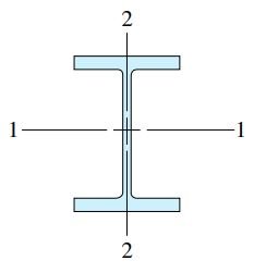
Place the origin of the x and y axes at the centroid C_{2} of the wide-flange section. Then the distances from the x axis to the centroids of the three areas are as follows:
\bar{y}_{1}=\frac{18.47 in.}{2}+\frac{0.5 in.}{2}=9.485 in.
\bar{y}_{2}=0 \quad \bar{y}_{3}=\frac{18.47 in.}{2}+0.649 in.=9.884 in.
in which the pertinent dimensions of the wide-flange and channel sections are obtained from Tables F-1 and F-3.
The area A and first moment Q_{x} of the entire cross section are obtained from Eqs.(D-6a and b) as
A=\sum\limits_{i=1}^{n} A_{i}=A_{1}+A_{2}+A_{3}= 3.0 in ^{2}+20.8 in ^{2}+8.82 in ^{2}=32.62 in ^{2}
Q_{x}=\sum\limits_{i=1}^{n} \bar{y}_{i} A_{i}=\bar{y}_{1} A_{1}+\bar{y}_{2} A_{2}+\bar{y}_{3} A_{3}
= (9.485 in.)\left(3.0 in ^{2}\right)+0-(9.884 in.)\left(8.82 in ^{2}\right)=-58.72 in ^{3}
Now find the coordinate \bar{y} to the centroid C of the composite area from Eq.(D-7b):
\bar{y}=\frac{Q_{x}}{A}=\frac{-58.72 in ^{3}}{32.62 in ^{2}}=-1.80 in.
Since ȳ is positive in the positive direction of the y axis, the minus sign means that the centroid C of the composite area is located below the x axis, as shown in Fig.D-8. Thus, the distance \bar{c} between the x axis and the centroid C is
\bar{c}=1.80 in.Note that the position of the reference axis (the x axis) is arbitrary; however, in this example it was placed through the centroid of the wide-flange section because it slightly simplifies the calculations.
| Table F-1(a) | ||||||||||||
| Properties of Wide-Flange Sections (W Shapes)—USCS Units (Abridged List) | ||||||||||||
| Designation | Weight per Foot |
Area | Depth | Web Thickness |
Flange | Axis 1–1 | Axis 2-2 | |||||
| Width | Thickness | I | S | r | I | S | r | |||||
| lb | in² | in. | in. | in. | in. | \text{in}^{4} | in³ | in. | \text{in}^{4} | in³ | in. | |
| W 30 × 211 | 211 | 62.2 | 30.9 | 0.775 | 15.1 | 1.32 | 10300 | 665 | 12.9 | 757 | 100 | 3.49 |
| W 30 × 132 | 132 | 38.9 | 30.3 | 0.615 | 10.5 | 1.00 | 5770 | 380 | 12.2 | 196 | 37.2 | 2.25 |
| W 24 × 162 | 162 | 47.7 | 25.0 | 0.705 | 13.0 | 1.22 | 5170 | 414 | 10.4 | 443 | 68.4 | 3.05 |
| W 24 × 94 | 94.0 | 27.7 | 24.3 | 0.515 | 9.07 | 0.875 | 2700 | 222 | 9.87 | 109 | 24.0 | 1.98 |
| W 18 × 119 | 119 | 35.1 | 19.0 | 0.655 | 11.3 | 1.06 | 2190 | 231 | 7.90 | 253 | 44.9 | 2.69 |
| W 18 × 71 | 71.0 | 20.8 | 18.5 | 0.495 | 7.64 | 0.810 | 1170 | 127 | 7.50 | 60.3 | 15.8 | 1.70 |
| W 16 × 100 | 100 | 29.5 | 17.0 | 0.585 | 10.4 | 0.985 | 1490 | 175 | 7.10 | 186 | 35.7 | 2.51 |
| W 16 × 77 | 77.0 | 22.6 | 16.5 | 0.455 | 10.3 | 0.760 | 1110 | 134 | 7.00 | 138 | 26.9 | 2.47 |
| W 16 × 57 | 57.0 | 16.8 | 16.4 | 0.430 | 7.12 | 0.715 | 758 | 92.2 | 6.72 | 43.1 | 12.1 | 1.60 |
| W 16 × 31 | 31.0 | 9.13 | 15.9 | 0.275 | 5.53 | 0.440 | 375 | 47.2 | 6.41 | 12.4 | 4.49 | 1.17 |
| W 14 × 120 | 120 | 35.3 | 14.5 | 0.590 | 14.7 | 0.940 | 1380 | 190 | 6.24 | 495 | 67.5 | 3.74 |
| W 14 × 82 | 82.0 | 24.0 | 14.3 | 0.510 | 10.1 | 0.855 | 881 | 123 | 6.05 | 148 | 29.3 | 2.48 |
| W 14 × 53 | 53.0 | 15.6 | 13.9 | 0.370 | 8.06 | 0.660 | 541 | 77.8 | 5.89 | 57.7 | 14.3 | 1.92 |
| W 14 × 26 | 26.0 | 7.69 | 13.9 | 0.255 | 5.03 | 0.420 | 245 | 35.3 | 5.65 | 8.91 | 3.55 | 1.08 |
| W 12 × 87 | 87.0 | 25.6 | 12.5 | 0.515 | 12.1 | 0.810 | 740 | 118 | 5.38 | 241 | 39.7 | 3.07 |
| W 12 × 50 | 50.0 | 14.6 | 12.2 | 0.370 | 8.08 | 0.640 | 391 | 64.2 | 5.18 | 56.3 | 13.9 | 1.96 |
| W 12 × 35 | 35.0 | 10.3 | 12.5 | 0.300 | 6.56 | 0.520 | 285 | 45.6 | 5.25 | 24.5 | 7.47 | 1.54 |
| W 12 × 14 | 14.0 | 4.16 | 11.9 | 0.200 | 3.97 | 0.225 | 88.6 | 14.9 | 4.62 | 2.36 | 1.19 | 0.753 |
| W 10 × 60 | 60.0 | 17.6 | 10.2 | 0.420 | 10.1 | 0.680 | 341 | 66.7 | 4.39 | 116 | 23.0 | 2.57 |
| W 10 × 45 | 45.0 | 13.3 | 10.1 | 0.350 | 8.02 | 0.620 | 248 | 49.1 | 4.32 | 53.4 | 13.3 | 2.01 |
| W 10 × 30 | 30.0 | 8.84 | 10.5 | 0.300 | 5.81 | 0.510 | 170 | 32.4 | 4.38 | 16.7 | 5.75 | 1.37 |
| W 10× 12 | 12.0 | 3.54 | 9.87 | 0.190 | 3.96 | 0.210 | 53.8 | 10.9 | 3.90 | 2.18 | 1.10 | 0.785 |
| W 8 × 35 | 35.0 | 10.3 | 8.12 | 0.310 | 8.02 | 0.495 | 127 | 31.2 | 3.51 | 42.6 | 10.6 | 2.03 |
| W 8 × 28 | 28.0 | 8.24 | 8.06 | 0.285 | 6.54 | 0.465 | 98.0 | 24.3 | 3.45 | 21.7 | 6.63 | 1.62 |
| W 8 × 21 | 21.0 | 6.16 | 8.28 | 0.250 | 5.27 | 0.400 | 75.3 | 18.2 | 3.49 | 9.77 | 3.71 | 1.26 |
| W 8 × 15 | 15.0 | 4.44 | 8.11 | 0.245 | 4.01 | 0.315 | 48.0 | 11.8 | 3.29 | 3.41 | 1.70 | 0.876 |
| Table F-1(b) | ||||||||||||
| Properties of Wide-Flange Sections (W Shapes)—SI Units (Abridged List) | ||||||||||||
| Designation | Mass per Meter | Area | Depth | Web Thickness |
Flange | Axis 1–1 | Axis 2-2 | |||||
| Width | Thickness | I | S | r | I | S | r | |||||
| Kg | mm² | mm | mm | mm | mm | ×10^{6}mm^{4} | ×10^{3}mm^{3} | mm | ×10^{6}mm^{4} | ×10^{3}mm^{3} | mm | |
| W 760 × 314 | 314 | 40100 | 785 | 19.7 | 384 | 33.5 | 4290 | 10900 | 328 | 315 | 1640 | 88.6 |
| W 760 × 196 | 196 | 25100 | 770 | 15.6 | 267 | 25.4 | 2400 | 6230 | 310 | 81.6 | 610 | 57.2 |
| W 610 × 241 | 241 | 30800 | 635 | 17.9 | 330 | 31.0 | 2150 | 6780 | 264 | 184 | 1120 | 77.5 |
| W 610 × 140 | 140 | 17900 | 617 | 13.1 | 230 | 22.2 | 1120 | 3640 | 251 | 45.4 | 393 | 50.3 |
| W 460 × 177 | 177 | 22600 | 483 | 16.6 | 287 | 26.9 | 912 | 3790 | 201 | 105 | 736 | 68.3 |
| W 460 × 106 | 106 | 13400 | 470 | 12.6 | 194 | 20.6 | 487 | 2080 | 191 | 25.1 | 259 | 43.2 |
| W 410 × 149 | 149 | 19000 | 432 | 14.9 | 264 | 25.0 | 620 | 2870 | 180 | 77.4 | 585 | 63.8 |
| W 410 × 114 | 114 | 14600 | 419 | 11.6 | 262 | 19.3 | 462 | 2200 | 178 | 57.4 | 441 | 62.7 |
| W 410 × 85 | 85.0 | 10800 | 417 | 10.9 | 181 | 18.2 | 316 | 1510 | 171 | 17.9 | 198 | 40.6 |
| W 410 × 46.1 | 46.1 | 5890 | 404 | 6.99 | 140 | 11.2 | 156 | 773 | 163 | 5.16 | 73.6 | 29.7 |
| W 360 × 179 | 179 | 22800 | 368 | 15.0 | 373 | 23.9 | 574 | 3110 | 158 | 206 | 1110 | 95.0 |
| W 360 × 122 | 122 | 15500 | 363 | 13.0 | 257 | 21.7 | 367 | 2020 | 154 | 61.6 | 480 | 63.0 |
| W 360 × 79 | 79.0 | 10100 | 353 | 9.40 | 205 | 16.8 | 225 | 1270 | 150 | 24.0 | 234 | 48.8 |
| W 360 × 39 | 39.0 | 4960 | 353 | 6.48 | 128 | 10.7 | 102 | 578 | 144 | 3.71 | 58.2 | 27.4 |
| W 310 × 129 | 129 | 16500 | 318 | 13.1 | 307 | 20.6 | 308 | 1930 | 137 | 100 | 651 | 78.0 |
| W 310 × 74 | 74.0 | 9420 | 310 | 9.40 | 205 | 16.3 | 163 | 1050 | 132 | 23.4 | 228 | 49.8 |
| W 310 × 52 | 52.0 | 6650 | 318 | 7.62 | 167 | 13.2 | 119 | 747 | 133 | 10.2 | 122 | 39.1 |
| W 310 × 21 | 21.0 | 2680 | 302 | 5.08 | 101 | 5.72 | 36.9 | 244 | 117 | 0.982 | 19.5 | 19.1 |
| W 250 × 89 | 89.0 | 11400 | 259 | 10.7 | 257 | 17.3 | 142 | 1090 | 112 | 48.3 | 377 | 65.3 |
| W 250 × 67 | 67.0 | 8580 | 257 | 8.89 | 204 | 15.7 | 103 | 805 | 110 | 22.2 | 218 | 51.1 |
| W 250 × 44.8 | 44.8 | 5700 | 267 | 7.62 | 148 | 13.0 | 70.8 | 531 | 111 | 6.95 | 94.2 | 34.8 |
| W 250 × 17.9 | 17.9 | 2280 | 251 | 4.83 | 101 | 5.33 | 22.4 | 179 | 99.1 | 0.907 | 18.0 | 19.9 |
| W 200 × 52 | 52.0 | 6650 | 206 | 7.87 | 204 | 12.6 | 52.9 | 511 | 89.2 | 17.7 | 174 | 51.6 |
| W 200 × 41.7 | 41.7 | 5320 | 205 | 7.24 | 166 | 11.8 | 40.8 | 398 | 87.6 | 9.03 | 109 | 41.1 |
| W 200 × 31.3 | 31.3 | 3970 | 210 | 6.35 | 134 | 10.2 | 31.3 | 298 | 88.6 | 4.07 | 60.8 | 32.0 |
| W 200 × 22.5 | 22.5 | 2860 | 206 | 6.22 | 102 | 8.00 | 20.0 | 193 | 83.6 | 1.42 | 27.9 | 22.3 |

| Table F-3(a) | |||||||||||||
| Properties of Channel Sections (C Shapes)—USCS Units (Abridged List) | |||||||||||||
| Designation | Weight per Foot |
Area | Depth | Web Thickness |
Flange | Axis 1–1 | Axis 2–2 | ||||||
| Width | Average Thickness |
I | S | r | I | S | r | c | |||||
| lb | in² | in. | in. | in. | in. | in^{4} | in³ | in. | in^{4} | in³ | in. | in. | |
| C 15 × 50 | 50.0 | 14.7 | 15.0 | 0.716 | 3.72 | 0.650 | 404 | 53.8 | 5.24 | 11.0 | 3.77 | 0.865 | 0.799 |
| C 15 × 40 | 40.0 | 11.8 | 15.0 | 0.520 | 3.52 | 0.650 | 348 | 46.5 | 5.45 | 9.17 | 3.34 | 0.883 | 0.778 |
| C 15 × 33.9 | 33.9 | 10.0 | 15.0 | 0.400 | 3.40 | 0.650 | 315 | 42.0 | 5.62 | 8.07 | 3.09 | 0.901 | 0.788 |
| C 12 × 30 | 30.0 | 8.81 | 12.0 | 0.510 | 3.17 | 0.501 | 162 | 27.0 | 4.29 | 5.12 | 2.05 | 0.762 | 0.674 |
| C 12 × 25 | 25.0 | 7.34 | 12.0 | 0.387 | 3.05 | 0.501 | 144 | 24.0 | 4.43 | 4.45 | 1.87 | 0.779 | 0.674 |
| C 12 × 20.7 | 20.7 | 6.08 | 12.0 | 0.282 | 2.94 | 0.501 | 129 | 21.5 | 4.61 | 3.86 | 1.72 | 0.797 | 0.698 |
| C 10 × 30 | 30.0 | 8.81 | 10.0 | 0.673 | 3.03 | 0.436 | 103 | 20.7 | 3.42 | 3.93 | 1.65 | 0.668 | 0.649 |
| C 10 × 25 | 25.0 | 7.34 | 10.0 | 0.526 | 2.89 | 0.436 | 91.1 | 18.2 | 3.52 | 3.34 | 1.47 | 0.675 | 0.617 |
| C 10 × 20 | 20.0 | 5.87 | 10.0 | 0.379 | 2.74 | 0.436 | 78.9 | 15.8 | 3.66 | 2.80 | 1.31 | 0.690 | 0.606 |
| C 10 × 15.3 | 15.3 | 4.48 | 10.0 | 0.240 | 2.60 | 0.436 | 67.3 | 13.5 | 3.87 | 2.27 | 1.15 | 0.711 | 0.634 |
| C 8 × 18.7 | 18.7 | 5.51 | 8.00 | 0.487 | 2.53 | 0.390 | 43.9 | 11.0 | 2.82 | 1.97 | 1.01 | 0.598 | 0.565 |
| C 8 × 13.7 | 13.7 | 4.04 | 8.00 | 0.303 | 2.34 | 0.390 | 36.1 | 9.02 | 2.99 | 1.52 | 0.848 | 0.613 | 0.554 |
| C 8 × 11.5 | 11.5 | 3.37 | 8.00 | 0.220 | 2.26 | 0.390 | 32.5 | 8.14 | 3.11 | 1.31 | 0.775 | 0.623 | 0.572 |
| C 6 × 13 | 13.0 | 3.81 | 6.00 | 0.437 | 2.16 | 0.343 | 17.3 | 5.78 | 2.13 | 1.05 | 0.638 | 0.524 | 0.514 |
| C 6 × 10.5 | 10.5 | 3.08 | 6.00 | 0.314 | 2.03 | 0.343 | 15.1 | 5.04 | 2.22 | 0.860 | 0.561 | 0.529 | 0.500 |
| C 6 × 8.2 | 8.20 | 2.39 | 6.00 | 0.200 | 1.92 | 0.343 | 13.1 | 4.35 | 2.34 | 0.687 | 0.488 | 0.536 | 0.512 |
| C 4 × 7.2 | 7.20 | 2.13 | 4.00 | 0.321 | 1.72 | 0.296 | 4.58 | 2.29 | 1.47 | 0.425 | 0.337 | 0.447 | 0.459 |
| C 4 × 5.4 | 5.40 | 1.58 | 4.00 | 0.184 | 1.58 | 0.296 | 3.85 | 1.92 | 1.56 | 0.312 | 0.277 | 0.444 | 0.457 |
| Notes: 1. Axes 1–1 and 2–2 are principal centroidal axes. 2. The distance c is measured from the centroid to the back of the web. 3. For axis 2–2, the tabulated value of S is the smaller of the two section moduli for this axis. |
|||||||||||||
| Table F-3(b) | |||||||||||||
| Properties of Channel Sections (C Shapes)—SI Units (Abridged List) | |||||||||||||
| Designation | Mass per Meter |
Area | Depth | Web Thickness |
Flange | Axis 1–1 | Axis 2–2 | ||||||
| Width | Thickness | I | S | r | I | S | r | c | |||||
| kg | mm² | mm | mm | mm | mm | ×10^{6}mm^{4} | ×10³mm³ | mm | ×10^{6}mm^{4} | ×10³mm³ | mm | mm | |
| C 380 × 74 | 74.0 | 9480 | 381 | 18.2 | 94.5 | 16.5 | 168 | 882 | 133 | 4.58 | 61.8 | 22.0 | 20.3 |
| C 380 × 60 | 60.0 | 7610 | 381 | 13.2 | 89.4 | 16.5 | 145 | 762 | 138 | 3.82 | 54.7 | 22.4 | 19.8 |
| C 380 × 50.4 | 50.4 | 6450 | 381 | 10.2 | 86.4 | 16.5 | 131 | 688 | 143 | 3.36 | 50.6 | 22.9 | 20.0 |
| C 310 × 45 | 45.0 | 5680 | 305 | 13.0 | 80.5 | 12.7 | 67.4 | 442 | 109 | 2.13 | 33.6 | 19.4 | 17.1 |
| C 310 × 37 | 37.0 | 4740 | 305 | 9.83 | 77.5 | 12.7 | 59.9 | 393 | 113 | 1.85 | 30.6 | 19.8 | 17.1 |
| C 310 × 30.8 | 30.8 | 3920 | 305 | 7.16 | 74.7 | 12.7 | 53.7 | 352 | 117 | 1.61 | 28.2 | 20.2 | 17.7 |
| C 250 × 45 | 45.0 | 5680 | 254 | 17.1 | 77.0 | 11.1 | 42.9 | 339 | 86.9 | 1.64 | 27.0 | 17.0 | 16.5 |
| C 250 × 37 | 37.0 | 4740 | 254 | 13.4 | 73.4 | 11.1 | 37.9 | 298 | 89.4 | 1.39 | 24.1 | 17.1 | 15.7 |
| C 250 × 30 | 30.0 | 3790 | 254 | 9.63 | 69.6 | 11.1 | 32.8 | 259 | 93.0 | 1.17 | 21.5 | 17.5 | 15.4 |
| C 250 × 22.8 | 22.8 | 2890 | 254 | 6.10 | 66.0 | 11.1 | 28.0 | 221 | 98.3 | 0.945 | 18.8 | 18.1 | 16.1 |
| C 200 × 27.9 | 27.9 | 3550 | 203 | 12.4 | 64.3 | 9.91 | 18.3 | 180 | 71.6 | 0.820 | 16.6 | 15.2 | 14.4 |
| C 200 × 20.5 | 20.5 | 2610 | 203 | 7.70 | 59.4 | 9.91 | 15.0 | 148 | 75.9 | 0.633 | 13.9 | 15.6 | 14.1 |
| C 200 × 17.1 | 17.1 | 2170 | 203 | 5.59 | 57.4 | 9.91 | 13.5 | 133 | 79.0 | 0.545 | 12.7 | 15.8 | 14.5 |
| C 150 × 19.3 | 19.3 | 2460 | 152 | 11.1 | 54.9 | 8.71 | 7.20 | 94.7 | 54.1 | 0.437 | 10.5 | 13.3 | 13.1 |
| C 150 × 15.6 | 15.6 | 1990 | 152 | 7.98 | 51.6 | 8.71 | 6.29 | 82.6 | 56.4 | 0.358 | 9.19 | 13.4 | 12.7 |
| C 150 × 12.2 | 12.2 | 1540 | 152 | 5.08 | 48.8 | 8.71 | 5.45 | 71.3 | 59.4 | 0.286 | 8.00 | 13.6 | 13.0 |
| C 100 × 10.8 | 10.8 | 1370 | 102 | 8.15 | 43.7 | 7.52 | 1.91 | 37.5 | 37.3 | 0.177 | 5.52 | 11.4 | 11.7 |
| C 100 × 8 | 8.00 | 1020 | 102 | 4.67 | 40.1 | 7.52 | 1.60 | 31.5 | 39.6 | 0.130 | 4.54 | 11.3 | 11.6 |
| Notes: 1. Axes 1–1 and 2–2 are principal centroidal axes. 2. The distance c is measured from the centroid to the back of the web. 3. For axis 2–2, the tabulated value of S is the smaller of the two section moduli for this axis. |
|||||||||||||