Question 1.10: A semicircular bracket assembly is used to support a steel s...
A semicircular bracket assembly is used to support a steel staircase in an office building. One design under consideration, referred to as the eccentric design, uses two separate L-shaped brackets, each having a clevis attached to a steel hanger rod to support the staircase (see Fig. 1-52). Photos of the bracket attachment and hanger rod in the eccentric design are shown below (see also Example 1-6).
The staircase designer would like to also consider a symmetric bracket design. The symmetric design uses a single hanger rod attached
by a clevis and pin to a T-shaped bracket in which the two separate L-brackets are attached along a vertical axis (see Figs. 1-52c and d). In
this design, the eccentric moment of the rod force about the z axis is eliminated.
In the symmetric design, the weight of the staircase and the connection itself, and any building occupants who are using the staircase, is estimated to result in a force of F_{r}= 9600 N in the single hanger rod. Use numerical values for dimensions of connection components given below. Determine the following stresses in the symmetric connection.
(a) Average in-plane shear stress in bolts 1 to 6.
(b) Bearing stress between the clevis pin and the bracket.
(c) Bearing stress between the clevis and the pin.
(d) Bolt forces in the z direction at bolts 1 and 4 due to moment about the x axis, and resulting normal stress in bolts 1 and 4.
(e) Bearing stress between the bracket and washer at bolts 1 and 4.
(f) Shear stress through the bracket at bolts 1 and 4.
Numerical data:
\begin{gathered}b_{1}=40 mm \quad r=50 mm \quad t_{b}=12 mm \quad d_{w}=40 mm \\d_{b}=18 mm \quad d_{\text {pin }}=38 mm \quad t_{c}=14 mm \\e_{z}=150 mm \quad d_{r}=40 mm \quad F_{r}=9600 N\end{gathered}


Learn more on how we answer questions.
As a starting point, we note that the normal tensile stress in the hanger rod is computed as the force in the rod (F_{r}) divided by the cross-sectional area of the rod:
\sigma_{\text {rod }}=\frac{F_{r}}{A_{r}}=\frac{9600 N }{\frac{\pi}{4}(40 mm )^{2}}=7.64 MPaNow, we consider how the force F_{r} in the rod is distributed to the various components of the connection (i.e., clevis, pin, bracket and bolts) resulting in normal, shear, and bearing stresses in the connection.
(a) The average in-plane shear stress in bolts 1 through 6 is equal to the force in the rod divided by the sum of the cross-sectional areas of the six bolts. This is based on the assumption that each bolt carries the same fraction of the overall rod force (see Fig. 1-52e):
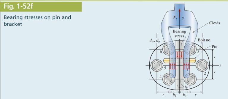
\tau_{\text {bolt }}=\frac{F_{r}}{6 A_{\text {bolt }}}=\frac{9600 N }{6\left[\frac{\pi}{4}(18 mm )^{2}\right]}=6.29 MPa(b) The bearing stress between the clevis pin and the bracket is shown in Fig. 1-52f. The pin bears against the center portion of the bracket which has thickness of twice the bracket plate thickness \left(t_{b}\right) so the bearing stress is computed as follows:
\sigma_{b 1}=\frac{F_{r}}{d_{\text {pin }}\left(2 t_{b}\right)}=\frac{9600 N }{(38 mm )(2 \times 12 mm )}=10.53 MPa(c) The clevis bears against the pin in two locations (see Fig. 1-52f) so the bearing stress between the clevis and the pin is computed as the rod force divided by twice the clevis thickness \left(t_{c}\right) times the pin diameter:
\sigma_{b 2}=\frac{F_{r}}{d_{\text {pin }}\left(2 t_{c}\right)}=\frac{9600 N }{(38 mm )(2)(14 mm )}=9.02 MPa(d) Although the connection bracket is symmetric with respect to the y_{z} plane, the rod force Fr is applied at a distance e_{z} = 150 mm from the back plate (see Fig. 1-52g). This results in a moment about the x axis M_{x}=F_{r} \times e_{z}which can be converted into two force couples, each equal to F_{z} \times 2 r , at bolt pairs 1–3 and 4–6. The resulting tension force on bolts 1 and 4 is computed as
F_{z}=\frac{M_{x}}{4 r}=\frac{F_{r} e_{z}}{4 r}=\frac{9600 N (150 mm )}{4(50 mm )}=7.2 kNHere, we have assumed that the moment F_{r} \times e_{z} acts about the x axis, which eliminates bolts 2 and 5 because they lie along the x axis (Fig. 1-52h). Using force F_{z}, we can now compute the normal stress in bolts 1 and 4 as
\sigma_{1}=\sigma_{4}=\frac{F_{z}}{\frac{\pi}{4} d_{b}^{2}}=\frac{7.2 kN }{\frac{\pi}{4}(18 mm )^{2}}=28.3 MPaNote that the bolts are likely to be pretensioned so the computed stress \sigma_{1} \text { or } \sigma_{4} is in fact the stress increase at bolts 1 and 4, respectively, and the stress decrease at bolts 3 and 6, respectively, due to the moment M_{x}.
Also, note that the symmetric bracket design eliminates the torsional moment about the z axis \left(M_{z}=F_{r} \times e_{x}\right) resulting from the application of the rod force at a distance e_{x} from the center of gravity of the bolt group in the eccentric bracket design.
(e) Now that we know the force F_{z} acting on bolts 1 and 4, we can compute the bearing stress between the bracket and washer at bolts 1 and 4. The bearing area is the ring-shaped area of the washer so the bearing stress is
\sigma_{b 3}=\frac{F_{z}}{\frac{\pi}{4}\left(d_{w}^{2}-d_{b}^{2}\right)}=\frac{7.2 kN }{\frac{\pi}{4}\left[(40 mm )^{2}-(18 mm )^{2}\right]}=7.18 MPa(f) Finally, the shear stress through the bracket at bolts 1 and 4 is the force F_{z} divided by the circumference of the washer times the thickness of the bracket:
\tau=\frac{F_{z}}{\pi d_{w} t_{b}}=\frac{7.2 kN }{\pi(40 mm )(12 mm )}=4.77 MPa