
This beam has four unknown reactions (a force and a moment at each sup-port), but only two independent equations of equilibrium are available. Therefore, the beam is statically indeterminate to the second degree. In this example, we will select the reactive moments M_{A} and M_{B} as the redundants.
Equations of equilibrium. The two unknown force reactions (R_{A} and R_{B}) can be expressed in terms of the redundants (M_{A} and M_{B}) with the aid of two equations of equilibrium. The first equation is for moments about point B, and the second is for moments about point A. The resulting expressions are
R_{A}=\frac{P b}{L}+\frac{M_{A}}{L}-\frac{M_{B}}{L} \quad R_{B}=\frac{P a}{L}-\frac{M_{A}}{L}+\frac{M_{B}}{L} (a,b)
Equations of compatibility. When both redundants are released by removing the rotational restraints at the ends of the beam, we are left with a simple beam as the released structure (Figs. 10-15b, c, and d). The angles of rotation at the ends of the released structure due to the concentrated load P are denoted \left(\theta_{A}\right)_{1} and \left(\theta_{B}\right)_{2} , as shown in Fig. 10-15b. In a similar man- ner, the angles at the ends due to the redundant M_{A} are denoted \left(\theta_{A}\right)_{2} and \left(\theta_{B}\right)_{2} , and the angles due to the redundant M_{B} are denoted \left(\theta_{A}\right)_{3} and \left(\theta_{B}\right)_{3} . Since the angles of rotation at the supports of the original beam are equal to zero, the two equations of compatibility a
\theta_{A}=\left(\theta_{A}\right)_{1}-\left(\theta_{A}\right)_{2}-\left(\theta_{A}\right)_{3}=0 (c)
\theta_{B}=\left(\theta_{B}\right)_{1}-\left(\theta_{B}\right)_{2}-\left(\theta_{B}\right)_{3}=0 (d)
in which the signs of the various terms are determined by inspection from the figures.
Force-displacement relations. The angles at the ends of the beam due to the load P (Fig. 10-15b) are obtained from Case 5 of Table G-2
Table G-2
Deflections and Slopes of Simple Beams
 |
v = deflection in the y direction (positive upward) v^{\prime} = dv/dx = slope of the deflection curve \delta_{c} = -v(L/2) = deflection at midpoint C of the beam (positive downward) x_{1} = distance from support A to point of maximum deflection \delta_{\max }=-v_{\max } = maximum deflection (positive downward) \theta_{A}=-v^{\prime}(0)= angle of rotation at left-hand end of the beam (positive clockwise) \theta_{B}=v^{\prime}(L) =angle of rotation at right-hand end of the beam (positive counterclockwise) EI = constant |
 |
\begin{aligned}&v=-\frac{q x}{24 E I}\left(L^{3}-2 L x^{2}+x^{3}\right) \\&v^{\prime}=-\frac{q}{24 E I}\left(L^{3}-6 L x^{2}+4 x^{3}\right) \\&\delta_{C}=\delta_{\max }=\frac{5 q L^{4}}{384 E I} \quad \theta_{A}=\theta_{B}=\frac{q L^{3}}{24 E I}\end{aligned} |
 |
\begin{aligned}&v=-\frac{q x}{384 E I}\left(9 L^{3}-24 L x^{2}+16 x^{3}\right) \quad\left(0 \leq x \leq \frac{L}{2}\right) \\&v^{\prime}=-\frac{q}{384 E I}\left(9 L^{3}-72 L x^{2}+64 x^{3}\right) \quad\left(0 \leq x \leq \frac{L}{2}\right) \\&v=-\frac{q L}{384 E I}\left(8 x^{3}-24 L x^{2}+17 L^{2} x-L^{3}\right) \quad\left(\frac{L}{2} \leq x \leq L\right) \\&v^{\prime}=-\frac{q L}{384 E I}\left(24 x^{2}-48 L x+17 L^{2}\right) \quad\left(\frac{L}{2} \leq x \leq L\right) \\&\delta_{C}=\frac{5 q L^{4}}{768 E I} \quad \theta_{A}=\frac{3 q L^{3}}{128 E I} \quad \theta_{B}=\frac{7 q L^{3}}{384 E I}\end{aligned} |
 |
\begin{aligned}&v=-\frac{q x}{24 L E I}\left(a^{4}-4 a^{3} L+4 a^{2} L^{2}+2 a^{2} x^{2}-4 a L x^{2}+L x^{3}\right) \quad(0 \leq x \leq a) \\&v^{\prime}=-\frac{q}{24 L E I}\left(a^{4}-4 a^{3} L+4 a^{2} L^{2}+6 a^{2} x^{2}-12 a L x^{2}+4 L x^{3}\right) \quad(0 \leq x \leq a) \\&v=-\frac{q a^{2}}{24 L E I}\left(-a^{2} L+4 L^{2} x+a^{2} x-6 L x^{2}+2 x^{3}\right) \quad(a \leq x \leq L) \\&v^{\prime}=-\frac{q a^{2}}{24 L E I}\left(4 L^{2}+a^{2}-12 L x+6 x^{2}\right) \quad(a \leq x \leq L) \\&\theta_{A}=\frac{q a^{2}}{24 L EI}(2 L-a)^{2} \quad \theta_{B}=\frac{q a^{2}}{24 L E I}\left(2 L^{2}-a^{2}\right)\end{aligned} |
 |
\begin{aligned}&v=-\frac{P X}{48 E I}\left(3 L^{2}-4 x^{2}\right) \quad v^{\prime}=-\frac{P}{16 E I}\left(L^{2}-4 x^{2}\right) \quad\left(0 \leq x \leq \frac{L}{2}\right) \\&\delta_{C}=\delta_{\max }=\frac{P L^{3}}{48 E I} \quad \theta_{A}=\theta_{B}=\frac{P L^{2}}{16 E I}\end{aligned} |
 |
\begin{aligned}&v=-\frac{P b x}{6 L E I}\left(L^{2}-b^{2}-x^{2}\right) \quad v^{\prime}=-\frac{P b}{6 L E I}\left(L^{2}-b^{2}-3 x^{2}\right) \quad(0 \leq x \leq a) \\&\theta_{A}=\frac{P a b(L+b)}{6 L E I} \quad \theta_{B}=\frac{P a b(L+a)}{6 L E I} \\&\text { If } a \geq b, \quad \delta_{C}=\frac{P b\left(3 L^{2}-4 b^{2}\right)}{48 E I} \text { If } a \leq b, \quad \delta_{C}=\frac{P a\left(3 L^{2}-4 a^{2}\right)}{48 E I} \\&\text { If } a \geq b, x_{1}=\sqrt{\frac{L^{2}-b^{2}}{3}} \text { and } \delta_{\max }=\frac{P b\left(L^{2}-b^{2}\right)^{3 / 2}}{9 \sqrt{3} L E I}\end{aligned} |
 |
\begin{array}{ll}v=-\frac{P X}{6 E I}\left(3 a L-3 a^{2}-x^{2}\right) & v^{\prime}=-\frac{P}{2 E I}\left(a L-a^{2}-x^{2}\right) \quad(0 \leq x \leq a) \\v=-\frac{P a}{6 E I}\left(3 L x-3 x^{2}-a^{2}\right) & v^{\prime}=-\frac{P a}{2 E I}(L-2 x) \quad(a \leq x \leq L-a) \\\delta_{C}=\delta_{\max }=\frac{P a}{24 E I}\left(3 L^{2}-4 a^{2}\right) \quad \theta_{A}=\theta_{B}=\frac{P a(L-a)}{2 E I}\end{array} |
 |
\begin{aligned}&v=-\frac{M_{0} x}{6 L E I}\left(2 L^{2}-3 L x+x^{2}\right) \quad v^{\prime}=-\frac{M_{0}}{6 L E I}\left(2 L^{2}-6 L x+3 x^{2}\right) \\&\delta_{C}=\frac{M_{0} L^{2}}{16 E I} \quad \theta_{A}=\frac{M_{0} L}{3 E I} \quad \theta_{B}=\frac{M_{0} L}{6 E I} \\&x_{1}=L\left(1-\frac{\sqrt{3}}{3}\right) \quad \text { and } \quad \delta_{\max }=\frac{M_{0} L^{2}}{9 \sqrt{3} E I}\end{aligned} |
 |
\begin{aligned}&v=-\frac{M_{0} X}{24 L E I}\left(L^{2}-4 x^{2}\right) \quad v^{\prime}=-\frac{M_{0}}{24 L E I}\left(L^{2}-12 x^{2}\right) \quad\left(0 \leq x \leq \frac{L}{2}\right) \\&\delta_{C}=0 \quad \theta_{A}=\frac{M_{0} L}{24 E I} \quad \theta_{B}=-\frac{M_{0} L}{24 E I}\end{aligned} |
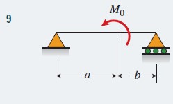 |
\begin{aligned}&v=-\frac{M_{0} x}{6 L E I}\left(6 a L-3 a^{2}-2 L^{2}-x^{2}\right) \quad(0 \leq x \leq a) \\&v^{\prime}=-\frac{M_{0}}{6 L E I}\left(6 a L-3 a^{2}-2 L^{2}-3 x^{2}\right) \quad(0 \leq x \leq a) \\&\text { At } x=a: v=\frac{M_{0} a b}{3 L E I}(2 a-L) \quad v^{\prime}=-\frac{M_{0}}{3 L E I}\left(3 a L-3 a^{2}-L^{2}\right) \\&\theta_{A}=\frac{M_{0}}{6 L E I}\left(6 a L-3 a^{2}-2 L^{2}\right) \quad \theta_{B}=\frac{M_{0}}{6 L E I}\left(3 a^{2}-L^{2}\right)\end{aligned} |
 |
\begin{aligned}&v=-\frac{M_{0} x}{2 E I}(L-x) \quad v^{\prime}=-\frac{M_{0}}{2 E I}(L-2 x) \\&\delta_{C}=\delta_{\max }=\frac{M_{0} L^{2}}{8 E I} \quad \theta_{A}=\theta_{B}=\frac{M_{0} L}{2 E I}\end{aligned} |
 |
\begin{aligned}&v=-\frac{q_{0} x}{360 L E I}\left(7 L^{4}-10 L^{2} x^{2}+3 x^{4}\right) \\&v^{\prime}=-\frac{q_{0}}{360 L E I}\left(7 L^{4}-30 L^{2} x^{2}+15 x^{4}\right) \\&\delta_{C}=\frac{5 q_{0} L^{4}}{768 E I} \quad \theta_{A}=\frac{7 q_{0} L^{3}}{360 E I} \quad \theta_{B}=\frac{q_{0} L^{3}}{45 E I} \\&x_{1}=0.5193 L \quad \delta_{\max }=0.00652 \frac{q_{0} L^{4}}{E I}\end{aligned} |
 |
\begin{aligned}&v=-\frac{q_{0} x}{960 L E I}\left(5 L^{2}-4 x^{2}\right)^{2} \quad\left(0 \leq x \leq \frac{L}{2}\right) \\&\left.v^{\prime}=-\frac{q_{0}}{192 L E I}\left(5 L^{2}-4 x^{2}\right) L^{2}-4 x^{2}\right) \quad\left(0 \leq x \leq \frac{L}{2}\right) \\&\delta_{C}=\delta_{\max }=\frac{q_{0} L^{4}}{120 E I} \quad \theta_{A}=\theta_{B}=\frac{5 q_{0} L^{3}}{192 E I}\end{aligned} |
 |
\begin{aligned}&v=-\frac{q_{0} L^{4}}{\pi^{4} E I} \sin \frac{\pi x}{L} \quad v^{\prime}=-\frac{q_{0} L^{3}}{\pi^{3} E I} \cos \frac{\pi x}{L} \\&\delta_{C}=\delta_{\max }=\frac{q_{0} L^{4}}{\pi^{4} E I} \quad \theta_{A}=\theta_{B}=\frac{q_{0} L^{3}}{\pi^{3} E I}\end{aligned} |
in which a and b are the distances from the supports to point D where the load is applied.
Also, the angles at the ends due to the redundant moment M_{A} are (see Case 7 of Table G-2):
Similarly, the angles due to the moment M_{B} are
\left(\theta_{A}\right)_{3}=\frac{M_{B} L}{6 E I} \quad\left(\theta_{B}\right)_{3}=\frac{M_{B} L}{3 E I}Reactions. When the preceding expressions for the angles are substi-tuted into the equations of compatibility [Eqs. (c) and (d)], we arrive at two simultaneous equations containing M_{A} and M_{B} as unknowns:
\frac{M_{A} L}{3 E I}+\frac{M_{B} L}{6 E I}=\frac{P a b(L+b)}{6 L E I} (e)
\frac{M_{A} L}{6 E I}+\frac{M_{B} L}{3 E I}=\frac{P a b(L+a)}{6 L E I} (f)
Solving these equations for the redundants, we obtain
M_{A}=\frac{P a b^{2}}{L^{2}} \quad M_{B}=\frac{P a^{2} b}{L^{2}} (10-30a,b)
Substituting these expressions for M_{A} and M_{B} into the equations of equilib-rium [Eqs. (a) and (b)], we obtain the vertical reactions
R_{A}=\frac{P b^{2}}{L^{3}}(L+2 a) \quad R_{B}=\frac{P a^{2}}{L^{3}}(L+2 b) (10-31a,b)
Thus, all reactions for the fixed-end beam have been determined.
The reactions at the supports of a beam with fixed ends are commonly referred to as fixed-end moments and fixed-end forces. They are widely used in structural analysis, and formulas for these quantities are listed in engineering handbooks.
Deflection at point D. To obtain the deflection at point D in the origi-nal fixed-end beam (Fig. 10-15a), we again use the principle of superpostion. The deflection at point D is equal to the sum of three deflections:
(1) the downward deflection \left(\delta_{D}\right)_{1} at point (δ D in the released structure due D )1 to the load P (Fig. 10-15b); (2) the upward deflection \left(\delta_{D}\right)_{2} at the same point in the released structure due to the redundant M_{A} (Fig. 10-15c); and (3) the upward deflection \left(\delta_{D}\right)_{3} at the same point in the released structure due to the redundant M_{B} (Fig. 10-15d). This superposition of deflections is expressed by the following equation:
\delta_{D}=\left(\delta_{D}\right)_{1}-\left(\delta_{D}\right)_{2}-\left(\delta_{D}\right)_{3} (g)
in which \left(\delta_{D}\right) is the downward deflection in the original beam.
The deflections appearing in Eq. (g) can be obtained from the formulas given in Table G-2 of Appendix G (see Cases 5 and 7) by making the appro-priate substitutions and algebraic simplifications. The results of these manipulations are as follows:
\left(\delta_{D}\right)_{1}=\frac{P a^{2} b^{2}}{3 L E I} \quad\left(\delta_{D}\right)_{2}=\frac{M_{A} a b}{6 L E I}(L+b) \quad\left(\delta_{D}\right)_{3}=\frac{M_{B} a b}{6 L E I}(L+a)Substituting the expressions for M_{A} and M_{B} from Eqs. (10-30a and b) into the last two expressions, we get
\left(\delta_{D}\right)_{2}=\frac{P a^{2} b^{3}}{6 L^{3}[I}(L+b) \quad\left(\delta_{D}\right)_{3}=\frac{P a^{3} b^{2}}{6 L^{7}[I}(L+a)Therefore, the deflection at point D in the original beam, obtained by sub-stituting \left(\delta_{D}\right)_{1},\left(\delta_{D}\right)_{2}, \text { and }\left(\delta_{D}\right) into Eq. (g) and simplifying, is
\delta_{D}=\frac{P a^{3} b^{3}}{3 L^{3} E I} (10-32)
The method described in this example for finding the deflection \delta_{D} can be used not only to find deflections at individual points, but also to find the equations of the deflection curve.
Concentrated load acting at the midpoint of the beam. When the load P acts at the midpoint C (Fig. 10-16), the reactions of the beam [from Eqs. (10-30) and (10-31) with a = b = L/2 ] are
M_{A}=M_{B}=\frac{P L}{8} \quad R_{A}=R_{B}=\frac{P}{2} (10-33a,b)
Also, the deflection at the midpoint [from Eq. (10-32)] is
\delta_{c}=\frac{P L^{3}}{192 E I} (10-34)
This deflection is only one-fourth of the deflection at the midpoint of a sim-ple beam with the same load, which shows the stiffening effect of clamping the ends of the beam.
The preceding results for the reactions at the ends and the deflection at the middle [Eqs. (10-32) and (10-33)] agree with those found in Example 10-2 by solving the differential equation of the deflection curve [see Eqs. (10-13)R_{A}=R_{B}=\frac{P}{2}, (10-14) M_{A}=M_{B}=\frac{P L}{8} , and (10-19) \delta_{\max }=-(v)_{x=L / 2}=\frac{P L^{3}}{192 E I} ].
