Known: Temperature of furnace surfaces and surroundings.
Find: Electrical power required to maintain four sections of the furnace at the prescribed temperature.
Schematic:
Assumptions:
1. Interior surfaces behave as blackbodies with uniform radiosity and irradiation.
2. Heat transfer by convection is negligible.
3. Backs of electrically heated surfaces are adiabatic.
Analysis: Subject to the foregoing assumptions, the only heat loss from the furnace is by radiation through the opening. Because the surroundings are large, the irradiation from the surroundings is equal to emission from a blackbody at T_{sur}, as discussed in Section 12.7. Furthermore, since radiation heat transfer between the furnace and the surroundings must pass through the opening, the radiation exchange may be analyzed as if it were between the furnace and a hypothetical black surface 5 at the opening, with T_{5} = T_{sur}. This approach is discussed in detail in Example 13.4. The electrical power delivered to each surface balances the corresponding radiation loss, which may be obtained from Equation 13.14. After employing Equation 13.3, we may write the following equations for surfaces 1 through 4.
q_{i} = \sum\limits_{j=1}^{N}A_{i}F_{ij}σ(T^{4}_{i} – T^{4}_{j}) (13.14)
A_{i}F_{ij} = A_{j}F_{ji} (13.3)
Surface 1: q_{1} = A_{1}F_{15}σ(T^{4}_{1} – T^{4}_{5}) = A_{5}F_{51}σ(T^{4}_{1} – T^{4}_{5}) (1)
Surface 2: q_{2} = A_{2}F_{25}σ(T^{4}_{2} – T^{4}_{5}) = A_{5}F_{52}σ(T^{4}_{2} – T^{4}_{5}) (2)
Surface 3: q_{3} = A_{3}F_{35}σ(T^{4}_{3} – T^{4}_{5}) = A_{5}F_{53}σ(T^{4}_{3} – T^{4}_{5}) (3)
Surface 4: q_{4} = A_{4}F_{45}σ(T^{4}_{4} – T^{4}_{5}) = A_{5}F_{54}σ(T^{4}_{4} – T^{4}_{5}) (4)
We will determine the view factors by first defining two hypothetical surfaces A′ and A′′ as shown in the schematic. From Table 13.2 with (r_{i}/L) = (r_{j}/L) = (0.025 m/0.150 m) = 0.167, F_{51} = 0.0263. With (r_{i}/L) = (r_{j}/L) = (0.025 m/0.100 m) = 0.25, F_{5A''} = 0.0557 so that F_{52} = F_{5A''} – F_{51} = 0.0557 – 0.0263 = 0.0294. Likewise, with (r_{i}/L) = (r_{j}/L) = (0.025 m/0.050 m) = 0.5, F_{5A'} = 0.172 so that F_{53} = F_{5A'} – F_{5A''} = 0.172 – 0.0557 = 0.1163. Finally, F_{54} = 1 – F_{5A'} = 1 – 0.172 = 0.828. The electrical power delivered to each of the four furnace surfaces can now be determined by solving Equations 1 through 4 for the radiation loss from each surface with A_{5} = \pi D^{2}/4 = \pi × (0.05 m)^{2}/4 = 0.00196 m^{2}.
| TABLE 13.2 View Factors for Three-Dimensional Geometries [4] | |
| Geometry | Relation |
| Aligned Parallel Rectangles (Figure 13.4)
|
\overline{X} = X/L, \overline{Y} = Y/L\\ F_{ij} = \frac{2}{\pi \overline{X}\overline{Y}}\left\{\ln \left[\frac{(1 + \overline{X}^{2})(1 + \overline{Y}^{2})}{1 +\overline{X}^{2}+ \overline{Y}^{2}}\right]^{1/2} + \overline{X}(1 + \overline{Y}^{2})^{1/2} \tan^{-1}\frac{\overline{X}}{(1 + \overline{Y}^{2})^{1/2}} + \overline{Y}(1 + \overline{X}^{2})^{1/2} \tan^{-1}\frac{\overline{Y}}{(1 + \overline{X}^{2})^{1/2}} – \overline{X} \tan^{-1} \overline{X} – \overline{Y} \tan^{-1} \overline{Y}\right\} |
| Coaxial Parallel Disks (Figure 13.5)
|
R_{i} = r_{i}/L, R_{j} = r_{j}/L\\ S = 1 + \frac{1 + R^{2}_{j}}{R^{2}_{i}}\\ F_{ij} = \frac{1}{2} \left\{S – [S^{2} – 4(r_{j}/r_{i})^{2}]^{1/2}\right\} |
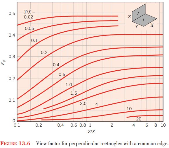
| Perpendicular Rectangles with a Common Edge (Figure 13.6)
|
H = Z/X, W = Y/X\\ F_{ij} = \frac{1}{\pi W} \left(W\tan^{-1} \frac{1}{W} + H \tan^{-1} \frac{1}{H} – (H^{2} + W^{2})^{1/2} \tan^{-1} \frac{1}{(H^{2} + W^{2})^{1/2}} + \frac{1}{4}\ln \left\{\frac{(1 + W^{2})(1 + H^{2})}{1 + W^{2} + H^{2}}\left[\frac{W^{2}(1 + W^{2} + H^{2})}{(1 + W^{2})(W^{2} + H^{2})}\right]^{W^{2}} \times \left[\frac{H^{2}(1 + H^{2} + W^{2})}{(1 + H^{2})(H^{2} + W^{2})}\right]^{H^{2}}\right\} \right) |


q_{1} = 0.00196 m^{2} × 0.0263 × 5.67 × 10^{-8} W/m^{2} · K^{4} × (1923 K^{4} – 300 K^{4}) = 39.9 W
q_{2} = 0.00196 m^{2} × 0.0294 × 5.67 × 10^{-8} W/m^{2} · K^{4} × (1923 K^{4} – 300 K^{4}) = 44.7 W
q_{3} = 0.00196 m^{2} × 0.1163 × 5.67 × 10^{-8} W/m^{2} · K^{4} × (1923 K^{4} – 300 K^{4}) = 177 W
q_{4} = 0.00196 m^{2} × 0.828 × 5.67 × 10^{-8} W/m^{2} · K^{4} × (1923 K^{4} – 300 K^{4}) = 1260 W
Comments:
1. Adding the view factors corresponding to surface 5 yields
F_{51} + F_{52} + F_{53} + F_{54} + F_{55} = 0.0263 + 0.0294 + 0.1163 + 0.828 + 0 = 1
Hence the enclosure rule, Equation 13.4, is satisfied, indicating that the view factors have been calculated correctly. Alternatively, the enclosure rule could have been utilized to determine one of the view factors used in the problem solution.
\sum\limits_{j=1}^{N}F_{ij} = 1 (13.4)
2. The radiation heat loss from the furnace is q_{tot} = q_{1} + q_{2} + q_{3} + q_{4} = 1522 W = 1.522 kW. If the furnace were to have been treated as a single surface f, the heat loss could be quickly calculated as q_{tot} = A_{5}F_{5 f} σ(T^{4}_{f} – T^{4}_{sur}) = 0.00196 m^{2} × 1 × 5.67 × 10^{-8} W/m^{2} · K × (1923 K^{4} – 300 K^{4}) = 1.522 kW. The answer is the same as determined in the problem solution since F_{5f} = 1 = F_{51} + F_{52} + F_{53} + F_{54} + F_{55}.
3. We have assumed that each surface i is isothermal and characterized by uniform radiosity, J_{i}, as well as uniform irradiation, G_{i}. Because the isothermal furnace walls are treated as blackbodies, J_{i} = E_{bi} and the assumption of uniform radiosity is valid. However, the irradiation distribution of the furnace surfaces is not uniform since, for example, irradiation from the cool surroundings influences the upper region of an annular surface more than the lower region. To quantify this effect, the local radiation heat flux along the vertical furnace wall may be determined by considering a ring element of differential area dA = πDdx as shown. Both sides of Equation 13.13 may be divided by dA yielding q''(x) = F_{dA – A_{5}}σ(T^{4}_{f} – T^{4}_{sur}) where the view factor from the differential ring element to the opening, area A_{5} is [4]
q_{ij} = A_{i}F_{ij}σ(T^{4}_{i} – T^{4}_{j}) (13.13)
F_{dA – A_{5}} = \frac{(x/D)^{2} + 1/2}{\sqrt{1 + (x/D)^{2}}} – x/D

Substituting the expression for F_{dA – A_{5}} into the equation for the heat flux q″(x) yields the heat flux distribution shown below. Also shown are the average heat fluxes associated with the three furnace segments, \overline{q''_{2}} = q_{2}/(\pi DL/3) = 44.7 W/(\pi × 0.05 m × 0.15 m/3) = 5690 W/m^{2} = 5.69 kW/m^{2}, \overline{q''_{3}} = q_{3}/(\pi DL/3) = 22.5 kW/m^{2}, and \overline{q''_{4}} = q_{4}/(\pi DL/3) = 160 kW/m^{2}.
Because of the nonuniformity of the irradiation along the sidewalls of the cavity, the local heat flux is highly nonuniform with the largest value occurring adjacent to the furnace opening. If local temperatures or heat fluxes are of interest, it is necessary to subdivide the various geometric surfaces into smaller radiative surfaces. This may be done either analytically, as demonstrated here, or numerically. Computational determination of local temperatures or heat fluxes may involve hundreds or perhaps thousands of radiative surfaces, even for simple geometries such as in this example.