Question 9.PE.1: To investigate the multiplexer For this exercise you will ne...
To investigate the multiplexer
For this exercise you will need the following components and equipment:
1 – 74LS153 ic (dual 4-to-1 multiplexer)
1 – +5 V dc power supply
1 – LED (5 mm) and series resistor (270 Ω)
The pin connection diagram for the 74153 ic is shown in Figure 9.5. The following details may be helpful:
The two separate multiplexers are referred to as (a) and (b).
D_0 to D_3 are the four data inputs. Q is the output. A and B are the two channel selection inputs.
With the EN (enable or strobe) input set at logic 1, the Q output will be logic 0. With the EN input at logic 0 (i.e. enabled), the Q output will take the logic level of the selected input.

Learn more on how we answer questions.
1 Connect up the circuit of Figure 9.6, which will use multiplexer(a).
2 Set the data word to D_0D_1D_2D_3 = 1101.
3 Work through the truth table (a), Figure 9.7, completing the column for the output Q, with the enable input (EN) initially at logic 1 and then at logic 0.
4 Work through the truth table (b), Figure 9.8, with the data inputs as shown.
Important points
• Each of the four lines of the truth table in Figure 9.7 represents the address of one of the data inputs.
• While that particular data input is being addressed, the logic level of the other data inputs is unimportant, that is, they are in a don’t care/doesn’t matter state, usually shown by an ‘X’ in the truth table (Figure 9.8).
• The output conditions of the truth table can be written as a Boolean expression. Hence from Figure 9.8 (and also from Figure 9.7) we can write
Z = \overline{A}.B.D_0 + A.B .D_1 + \overline{A}.B.D_2 + A.B.D_3
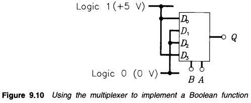
• Multiplexers can be used to implement a Boolean expression. For example, suppose that we wish to implement the logic statement given by
Z = \overline{A}.\overline{B} + A.B
The truth table is given in Figure 9.9 and shows the two input conditions that will produce a logic 1 output, namely when data inputs D_0 and D_3 equal 1.
Note that the complete expression for Ζ is given by
Z = \overline{A}.\overline{B}.D_0 + A.B .D_3
The implementation is shown in Figure 9.10 and can be tested in the next practical exercise.