Question 10.5: A steel shaft and an aluminum tube are connected to a fixed ...
A steel shaft and an aluminum tube are connected to a fixed support and to a rigid disk as shown in the cross section. Knowing that the initial stresses are zero, determine the maximum torque \pmb{\text{T}}_0 that can be applied to the disk if the allowable stresses are 120 MPa in the steel shaft and 70 MPa in the aluminum tube. Use G = 77 GPa for steel and G = 27 GPa for aluminum.

Learn more on how we answer questions.
STRATEGY: We know that the applied load is resisted by both the shaft and the tube, but we do not know the portion carried by each part. Thus we need to look at the deformations. We know that both the shaft and tube are connected to the rigid disk and that the angle of twist is therefore the same for each. Once we know the portion of the torque carried by each part, we can use the allowable stress for each to determine which one governs and use this to determine the maximum torque.
MODELING:
We first draw a free-body diagram of the disk (Fig. 1) and find
T_0=T_1+T_2 \quad \quad \quad \quad \quad \pmb{(1)}
Knowing that the angle of twist is the same for the shaft and tube, we write
\phi_1=\phi_2: \ \ \ \ \frac{T_1L_1}{J_1G_1} =\frac{T_2L_2}{J_2G_2} \\ \frac{T_1(0.5 \text{ m})}{(2.003 \times 10^{-6}\text{ m}^4)(27 \text{ GPa})}=\frac{T_2(0.5 \text{ m})}{(0.614 \times 10^{-6}\text{ m}^4)(77 \text{ GPa})} \\ T_2=0.874T_1 \quad \quad \quad \quad \pmb{(2)}
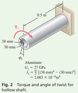
ANALYSIS: We need to determine which part reaches its allowable stress first, and so we arbitrarily assume that the requirement \tau_{\text{alum}}\leq 70 \text{ MPa} is critical. For the aluminum tube in Fig. 2, we have
T_1=\frac{\tau_{\text{alum}}J_1}{c_1} =\frac{(70 \text{ MPa})(2.003 \times 10^{-6}\text{ m}^4)}{0.038 \text{ m}}=3690 \text{ N} · \text{m}
Using Eq. (2), compute the corresponding value T_2 and then find the maximum shearing stress in the steel shaft of Fig. 3.
T_2=0.874T_1=0.874(3690)=3225 \text{ N} · \text{m} \\ \tau_{\text{steel}}=\frac{T_2c_2}{J_2}=\frac{(3225 \text{ N} · \text{m})(0.025 \text{ m})}{0.614 \times 10^{-6}\text{ m}^4} =131.3 \text{ MPa}
Note that the allowable steel stress of 120 MPa is exceeded; the assumption was wrong. Thus, the maximum torque \pmb{\text{T}}_0 will be obtained by making \tau_{\text{steel}}=120 \text{ MPa}. Determine the torque \pmb{\text{T}}_2:
T_2=\frac{\tau_{\text{steel}}J_2}{c_2}=\frac{(120 \text{ MPa})(0.614 \times 10^{-6}\text{ m}^4)}{0.025 \text{ m}}=2950 \text{ N} · \text{m}
From Eq. (2), we have
2950\text{ N} ·\text{m}=0.874T_1 \ \ \ \ \ T_1=3375 \text{ N}·\text{m}
Using Eq. (1), we obtain the maximum permissible torque:
T_0=T_1+T_2=3375\text{ N}·\text{m}+2950\text{ N}·\text{m}
T_0=6.325 \text{ N}·\text{m}
REFLECT and THINK: This example illustrates that each part must not exceed its maximum allowable stress. Since the steel shaft reaches its allowable stress level first, the maximum stress in the aluminum shaft is below its maximum.