Question 22.2: VARIOUS WASTE MANAGEMENT OPTIONS AND AN EXAMPLE FOR A COMPLE...
VARIOUS WASTE MANAGEMENT OPTIONS AND AN EXAMPLE FOR A COMPLETE WASTE TREATMENT AND RECYCLE SYSTEM FOR A CONVENTIONAL WATER TREATMENT PLANT
In Example 22.1, two very simple WTP waste management processes are illustrated. Not so many municipalities are fortunate to have compatible WWTP nearby to reuse WTP waste or to have large lagoons to perform all-in-one functions—waste collection, flow equalization, solids settling, water discharge, and sludge thickening/drying. Common WTP waste management methods can be various combinations of the following sub-methods:
1. The unregulated filter-to-waste:
(a) Recycle the unregulated filter-to-waste to rapid mixing basin.
(b) Recycle the unregulated filter-to-waste to the plant intake.
(c) Discharge the unregulated filter-to-waste to presedimentation reservoir or receiving water.
(d) Discharge the unregulated filter-to-waste to an equalization basin or lagoon.
2. The regulated clarifier sludge:
(a) Discharge the regulated clarifier sludge (sedimentation clarifier, DAF clarifier) to a sludge thickener (DAF thickener, gravity thickener) from where the thickened sludge is hauled away for sludge drying bed disposal or long-term lagoon storage.
(b) Discharge the regulated clarifier sludge (sedimentation clarifier, DAF clarifier) to a sludge thickener (DAF thickener, gravity thickener) from where the thickened sludge is hauled away for WWTP phosphate precipitation.
(c) Discharge the regulated clarifier sludge (sedimentation clarifier, DAF clarifier) to a sludge thickener (DAF thickener, gravity thickener) from where the thickened sludge is discharged to a sludge dewatering unit (filter press, centrifuge) from where the dewatered sludge is hauled away for landfill disposal.
(d) Discharge the regulated clarifier sludge (sedimentation clarifier, DAF clarifier) to a sludge thickener (DAF thickener, gravity thickener) from where the thickened sludge is discharged to a sludge dewatering unit (filter press, centrifuge) from where the dewatered sludge is hauled away to WWTP for phosphate precipitation.
3. The regulated spent filter backwash:
(a) Discharge the regulated spent filter backwash to an equalization basin or lagoon, from where the supernatant is recycled to the plant intake.
(b) Discharge the regulated spent filter backwash to an equalization basin or lagoon, from where the supernatant is discharged to a receiving water with NPDES/SPDES permit.
(c) Discharge the regulated spent filter backwash to an equalization basin or lagoon, from where the supernatant is discharged or pumped to a physicochemical wastewater treatment (PCWWT) unit (coagulation-sedimentation, coagulation-DAF, microsand, membrane filtration, etc.) from where the treated water is recycled to the presedimentation reservoir or plant intake.
(d) Discharge the regulated spent filter backwash to an equalization basin or lagoon, from where the supernatant is discharged or pumped to a PCWWT unit (coagulation-sedimentation, coagulation-DAF, microsand, membrane filtration, etc.) from where the treated water is combined with the dewatering unit effluent (water portion) for further PCWWT before it is recycled to the presedimentation reservoir or plant intake.
(e) Discharge the regulated spent filter backwash to a WWTP for removal of phosphate.
(f) Combine the regulated spent filter backwash and the regulated thickener effluent (water portion) in an equalization basin for subsequent treatment in a PCWWT unit (coagulation-sedimentation, coagulation-DAF, microsand, membrane filtration, etc.), from where the PCWWT effluent is combined with the water effluent of dewatering unit (filter press or centrifuge) for a second PCWWT before the water is recycled to the presedimentation reservoir or plant intake.
(g) Recycle the supernatant of gravity thickener (water portion) or the subnatant of DAF thickener (water portion) to the plant intake.
(h) Recycle the supernatant of gravity thickener (water portion) or the subnatant of DAF thickener (water portion) to presedimentation reservoir.
(i) Discharge the supernatant of gravity thickener (water portion) or the subnatant of DAF thickener (water portion) to a receiving water with NPDES/SPDES permit.
(j) Combine the thickener effluent (water portion) with the spent filter backwash in an equalization basin for further treatment in a PCWWT unit (coagulation-sedimentation, coagulation-DAF, microsand, membrane filtration, etc.), from where the PCWWT effluent is recycled to the plant intake or presedimentation reservoir.
(k) Combine the thickener effluent (water portion), spent filter backwash, and the dewatering unit effluent (water portion) together in an equalization basin for further PCWWT, and the PSWWT effluent is recycled to presedimentation reservoir or plant intake.
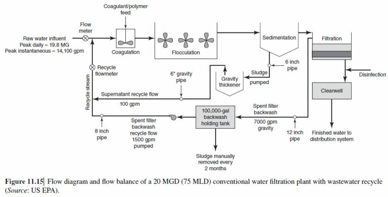
The functions of sludge thickening and sludge dewatering are both for sludge volume reduction. When both thickening and dewatering are used, the number of sludge treatment steps doubles, the overall sludge handling and treatment costs may actually decrease. A water engineer must design various feasible waste treatment systems (such as those shown in Figs. 11.9, 11.10, 11.11, 11.15, etc.) and conduct cost analyses for comparison, in order to find an optimized waste treatment system for a specific community. The best waste treatment system for Community A may not be the best waste treatment system for Community B because many local factors must be considered. In addition, if the raw water contains toxic substances, after proper water treatment, the finished water is potable and drinkable, but the toxic substances are nowconcentrated in the collectedwaste sludge and spent filter backwashwastewater.
Under this situation, the waste management method may become complex. Recommend a flow diagram of a complete conventional WTP consisting of (a) a water treatment train consisting of screening, pumping, raw water reservoir (presedimentation), chemical feeding, rapid mixing (flash mixing), coagulation/flocculation, sedimentation, filtration, corrosion control, secondary disinfection, and clearwell; and (b) a waste treatment train consisting of gravity thickening and plate frame press (filter press) dewatering for sludge treatment and equalization flocculation clarification for wastewater treatment.


Learn more on how we answer questions.
Select the following sub-methods from the above list:
1c. Discharge the unregulated filter-to-waste to presedimentation reservoir or receiving water.
2c. Discharge the regulated clarifier sludge (sedimentation clarifier, DAF clarifier) to a sludge thickener (DAF thickener, gravity thickener) from where the thickened sludge is discharged to a sludge dewatering unit (filter press, centrifuge) from where the dewatered sludge is hauled away for landfill disposal.
3f. Combine the regulated spent filter backwash and the regulated thickener effluent (water portion) in an equalization basin for subsequent PCWWT unit (coagulation-sedimentation, coagulation-DAF, microsand, membrane filtration, etc.), from where the PCWWT effluent is combined with the water effluent of dewatering unit (filter press or centrifuge) for a second PCWWT before the water is recycled to the presedimentation reservoir or plant intake.
Using the sub-methods 1c, 2c, and 3f, a complete flow diagram of a conventional WTP including both potable water treatment train and the waste management train can be constructed. Four assumptions are made for the construction of the flow diagram shown in Fig. 22.5:
1. Sedimentation (instead of dissolved air flotation) is used for water clarification.
2. Gravity thickener (instead of DAF thickener) is used for sludge thickening.
3. Plate frame press or filter press (instead of centrifuge) is used for dewatering.
4. Two-stage coagulation and flocculation (instead of other PCWWT) is used for treatment of wastewater.
Figure 22.5 illustrates the conventional WTP with the above specified waste sludge and wastewater treatment facilities. The most common water treatment units, such as screening, pumping, chemical feeding, corrosion control, primary and secondary disinfection, water storage, and water distribution, are not shown in Fig. 22.5 for the purpose of simplicity.
