Question 14.6.5: (Contributed by Professor J Heyman.) The pitched-roof frame ...
(Contributed by Professor J Heyman.) The pitched-roof frame in Fig. 14.6-12(a) is of uniform members having plastic moment of resistance 90 kN m; loads V and H are applied as shown. Plot an interaction diagram from which may be read the positive values of V and H which will just cause collapse of the frame.

Learn more on how we answer questions.
The frame has 5 critical sections and three redundancies; hence (see Eqn 14.6-3) there are two independent mechanisms.
M = N – R (14.6-3)}
We can immediately identify the pure sidesway mechanism in Fig. 14.6-12(b) and the part sidesway mechanism in Fig. 14.6-12(c); these are certainly independent (why?). Another possible mechanism is that in Fig. (d), which is obtained by adding together the mechanisms in Figs, (b) and (c)—see Comment (3) at the end of this Example.
For the collapse mechanism (b), the work equation is:
(4.5θ)H = (4) (90) θ
Or H = 80 (14.6-4)
For the collapse mechanism (c), the relative values of the hinge rotations and displacements are conveniently obtained by the method of instantaneous centre referred to earlier in Section 6.8. Referring to Fig. 14.6-12(c) the locus of joint Cʹ is perpendicular to BCʹ and that of joint Dʹ perpendicular to EDʹ. Therefore the instantaneous centre of rotation of the member CʹDʹ is located as the intersection I, of BCʹ and EDʹ produced. Consider a rotation θ of member BCʹ. Then
\hspace{5em} CC^\prime = \theta (BC^\prime )=\phi (IC^\prime )Or \hspace{2em} \phi = \left(\frac{BC^\prime}{IC^\prime} \right) \theta =\left(\frac{6}{3} \right)\theta =2\theta
Similarly DD^\prime = \phi (ID^\prime)=\beta (ED^\prime)
Or \beta =\left(\frac{ID^\prime}{ED^\prime} \right) \phi =\left(\frac{4.5}{4.5} \right) \phi =\phi
Therefore the hinge rotations are
\qquad \begin{matrix} \theta _{B} & = & \theta \qquad \qquad \\ \theta _{C} & = & \theta +\phi =3\theta \\ \theta _{D} & = & \phi +\beta =4\theta \\ \theta _{E} & =& \qquad \beta =2\theta \end{matrix}Also, the vertical component of the displacement C’C is
\qquad \Delta _{C}=(3)(\phi )=6\thetaThe horizontal displacement D’D is
\qquad \Delta _{D}=(4.5)(\beta )=(4.5)(2\theta)=9\thetaThe work equation is therefore
\qquad V(6\theta)+H(9\theta)=90(\theta+3\theta+4\theta+2\theta)Or \qquad 2V+3H=300 (14.6-5)
For the mechanism in Fig. 14.6-12(d), the instantaneous centre of rotation of the member C’D’ is located as the intersection, I of AC‘ and ED’ produced. The reader should verify that, if θA = θ then θC = 3θ, θD = 5θ, θE = 3θ, ΔC = 6θ, and D’D = 13.5θ. Therefore the work equation for this collapse mechanism is
V(6θ) + H( 13.5θ) = 90(θ + 3θ + 5θ + 3θ)
or 6V + 13.5H = 1080 (14.6-6)
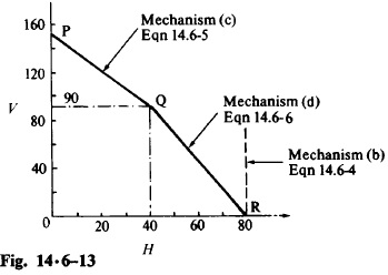
Using Eqns 14.6-4, 5 and 6, an interaction diagram may be plotted as in Fig.14.6-13. Any combination (V,H) which is represented by a point on the boundary PQR would just cause collapse; if the point lies on PQ, then collapse is occurring by the mechanism of Fig. 14.6-12(c); if it lies on QR, then collapse is occurring by the mechanism of Fig. 14.6-12(d). A point inside the bounded region OPQR represents combinations of (V,H) which are safe; a point outside OPQR represents load combinations which cannot be carried by the frame. The point Q(V = 90, H = 40) represents the load combination for which either of the two mechanisms in Figs. 14.6-12(c) and (d) can form. Similarly, the point R represents that load combination for which either of the mechanisms in Figs. 14.6-12(b) and (d) may occur. The interaction diagram also shows that, except when H = 80, the sideways mechanism (b) is not critical.
COMMENTS
(1) Interaction diagrams of the type shown in Fig. 14.6-13 are always convex round the origin; they cannot contain re-entrant angles. Suppose, for example, two collapse mechanisms are represented by the lines PQX and YQR in Fig. 14.6-14(a). To prove that the boundary YQX, having a re-entrant angle at Q, is not acceptable, it is only necessary to show that for any load path it is not possible for the collapse load combination p’ on the line QX to be reached before the combination p on the line QR.
(2) Suppose there exists in addition to the mechanisms in Fig. 14.6-12 another collapse mechanism represented by the line ST in Fig. 14.6-14(b), then, following the argument in Comment (1) above, the point P (and indeed any point within the whole shaded area near P) would represent a load combination that cannot be carried by the frame. Similarly, if there is a collapse mechanism represented by the line JK, then Q would be outside the safe region. Thus, to establish that an interaction diagram is complete for a complex frame in which the collapse mechanisms are not self evident, and one or more of which might have been overlooked, one need only show that points such as Q are “possible” in the sense that the yield condition is not violated.
(3) Finally, the reader should verify that the mechanism in Fig. 14.6-12(d) is not independent of those in Figs, (b) and (c), but is the result of adding together the latter two mechanisms. This being so, one would expect the work equation for the combined mechanism to be the sum of those for other two mechanisms. However, this is not quite true; the reader should add together Eqns 14.6-4 and 5 and verify that Eqn14.6-6 results only if an amount 2M_Pθ_B , which is equal to twice the plastic work term for the hinge B, is deducted from the total amount of plastic work absorbed in the frame. The reason for this deduction will be explained in the next section.