Question 5.13: Inductor Current and Voltage Consider the circuit shown in F...
Inductor Current and Voltage
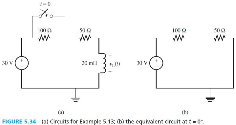
Consider the circuit shown in Figure 5.34. The switch closes at t = 0 after being opened for a long time period. Find i_{L}\left(0^{+}\right), v_{L}\left(0^{+}\right), and i_{L}(\infty).
The blue check mark means that this solution has been answered and checked by an expert. This guarantees that the final answer is accurate.
Learn more on how we answer questions.
Learn more on how we answer questions.
For t < 0, the switch is open for a long time period. Therefore, the inductor can be represented by a short circuit and the equivalent circuit is shown in Figure 5.34(b). The inductor current can be calculated as follows:
\begin{aligned}i_{L}\left(0^{+}\right)=i_{L}\left(0^{-}\right) &=\frac{30}{100+50} \\&=0.2 A\end{aligned}Closing the switch short-circuits the 100-Ω resistor. As a result:
\begin{aligned}v_{L}\left(0^{+}\right) &=30-50 \times i_{L}\left(0^{+}\right) \\&=30-50 \times 0.2 \\&=20 V\end{aligned}At t = ∞ , or steady state, the inductor becomes a short circuit. Thus:
i_{L}(\infty)=\frac{30}{50}=0.6 ARelated Answered Questions
Question: 5.9
Verified Answer:
KCL for Node A corresponds to:
-i_{s}+i_{R}...
Question: 5.10
Verified Answer:
This problem can be solved in a way similar to the...
Question: 5.11
Verified Answer:
a. The inductor is an open circuit at t = 0; thus,...
Question: 5.12
Verified Answer:
Before opening the switch (i.e., t < 0), the ci...
Question: 5.14
Verified Answer:
The equivalent circuit at t=0^{+}(a...
Question: 5.15
Verified Answer:
To find the circuit's conditions, calculate parame...
Question: 5.8
Verified Answer:
Using the definition of v_{C}(t)=V_{S}\left...
Question: 5.5
Verified Answer:
In Figure 5.18, the switch has been closed for a l...
Question: 5.4
Verified Answer:
a. After a long time period of the switch being in...
Question: 5.3
Verified Answer:
Because the switch was closed for a long time, the...