Question 9.12: Objective: Design an amplifier system that will produce an o...
Objective: Design an amplifier system that will produce an output voltage of ±5 V when the resistance R_{3} deviates by ±1% from the value of R_{2}. This would occur, for example, in a system where R_{3} is a thermistor whose resistance is given by
R_{3} = 200 \left[1 + \frac{(0.040)(T − 300)}{300} \right] kΩwhere T is the absolute temperature. For R_{3} to vary by ±1% means the temperature is in the range 225 ≤ T ≤ 375 K.
Consider biasing the bridge circuit at V^{+} = 7.5 V using a 5.6 V Zener diode.
Assume ±10 V is available for biasing the op-amp and reference voltage source, and that R_{1} = R_{2} = 200 kΩ .
Learn more on how we answer questions.
With R_{1} = R_{2}, from Equation (9.100), we have
v_{O1} = δ \left(\frac{R_{1}||R_{2}}{R_{1} + R_{2}} \right) V^{+} (9.100)
v_{O1} = \left(\frac{δ}{4} \right) V^{+}
For V^{+} = 7.5 V and δ = 0.01, the maximum output of the bridge circuit is v_{O1} = 0.01875 V. If the output of the amplifier system is to be +5 V, the gain of the instrumentation amplifier must be 5/0.01875 = 266.7. Consider the instrumentation amplifier shown in Figure 9.26. The output voltage is given by Equation (9.67), which can be written
v_{O} = \frac{R_{4}}{R_{3}} \left(1 + \frac{2 R_{2}}{R_{1}} \right) (v_{I2} − v_{I1}) (9.67)
\frac{v_{O}}{v_{O1}} = \frac{R_{4}^\prime}{R_{3}^\prime} \left(1 + \frac{2 R_{2}^\prime}{R_{1}^\prime} \right) = 266.7
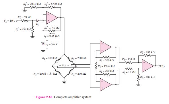
We would like the ratios R_{4}^\prime/R_{3}^\prime and R_{2}^\prime/R_{1}^\prime to be the same order of magnitude. If we let R_{3}^\prime = 15.0 k \Omega and R_{4}^\prime = 187.0 k\Omega , then R_{4}^\prime/R_{3}^\prime = 12.467 and R_{2}^\prime/R_{1}^\prime = 10.195. If we set R_{2}^\prime = 200.0 k \Omega, then R_{1}^\prime = 19.62 k\Omega.
Resistance R_{1}^\prime can be a combination of a fixed resistance in series with a potentiometer, to permit adjustment of the gain.
Comment: The complete design of this instrumentation amplifier is shown in Figure 9.45. Correlation of the reference voltage source design is left as an exercise.
Design Pointer: The design of fairly sophisticated op-amp circuits is quite straightforward when the ideal op-amp parameters are used.