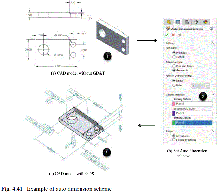
Question 4.5: Figure 4.41a shows the dimensions of a machined part. Use th...
Figure 4.41a shows the dimensions of a machined part. Use the AutoDimensionScheme tool tin DimXpert o annotate GD&T information automatically.

The blue check mark means that this solution has been answered and checked by an expert. This guarantees that the final answer is accurate.
Learn more on how we answer questions.
Learn more on how we answer questions.
Firstly, the part is modeled based on the dimensions specified in Fig. 4.41a. Secondly, the AutoDimensionScheme tool is used to specify (1) the part type; (2) tolerance type; (3) the pattern dimensioning; and most importantly, the primary, secondary, and tertiary references (see Fig. 4.41b). Thirdly, the AutoDimensionScheme tool is executed to create G&D annotations automatically.
Related Answered Questions
Question: 4.10
Verified Answer:
The milling operation is to create the profile of ...
Question: 4.9
Verified Answer:
By using APT, the NC program is written and shown ...
Question: 4.8
Verified Answer:
The incremental coordinates of a new working point...
Question: 4.7
Verified Answer:
The absolute coordinates are measured from origin ...
Question: 4.6
Verified Answer:
Based on the provided information, the workpiece a...
Question: 4.4
Verified Answer:
Firstly, the basic size is used to locate the roww...
Question: 4.3
Verified Answer:
Equation (4.10) is used to evaluate the maximum an...
Question: 4.2
Verified Answer:
For the baseline dimensioning in Fig. 4.33a, the d...
Question: 4.1
Verified Answer:
The Solidwork Simulation is used to analyze a comp...