Question 13.26: PSpice Analysis A DC shunt motor is designed to drive a load...
PSpice Analysis
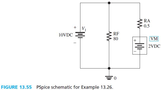
A DC shunt motor is designed to drive a load in the range of 20 to 50 N. The armature resistance, R_A, and the field resistance, R_F, are 0.5 and 80 Ω, respectively. In addition, assume the torque–emf relationship is T = K_A E_A where K_A = 10; note that this relationship can be maintained using Equations (13.24) and (13.25) , in which K_A = I_A / \omega_m. Use PSpice to simulate and plot the power consumed by the motor assuming the voltage supply is 10 V.
E_A = K \cdot K_1 \cdot \omega I_A (13.24)
T=K \cdot K_1 \cdot I_{A}^2 (13.25)
Learn more on how we answer questions.
First, determine the induced emf by the motor, which is:
E_A=\frac{T}{K_A}Using this equation and given the range of torque is 20 to 50 N, the range of induced emf is calculated as 2 to 5 V. Assume that the induced emf is a voltage source. The PSpice circuit is shown in Figure 13.55.
Here, the label of voltage source, “VM” (in the colored box) represents the induced emf produced by the motor. The label of any components in PSpice can be renamed by doubleclicking on the label (such as the “VM” inside the colored box).
Next, simulate the circuit for a given range of induced emf. Set the analysis type of the simulation to “DC sweep” (colored solid arrow in Figure 13.56). Then, determine which voltage source needs to be swept in the simulation, that is, the induced emf, “VM” (dashed arrow).
The minimum and maximum induced emf is set to 2 and 5 V, respectively. Using an appropriate increment, the sweep type is selected to be linear (black arrow), with the minimum and maximum induced emf obtained from the calculation (dotted arrow).
The PSpice Add Trace menu allows us to plot various expressions for the circuit using the basic expression of mathematic functions. Then, to plot the power consumed by motor, first, go to the Add Trace menu. The power consumed by an electronic device corresponds to P = V . I. Here, V is the voltage across the motor (also known as induced emf), and I is the current flow through the motor. Then, inside the Trace Expression column (see the arrow in Figure 13.57), type input “V(VM:+,VM,-)*I(VM).” Here, “V(VM:+,VM,-)” is the voltage across the motor, and I(VM) is the current flow through the motor and the symbol “*” represents the multiplication between two variables. The simulation plot is shown in Figure 13.58.