Question 26.7: Consider a MIMO process having a nominal model given by Go(s...
Consider a MIMO process having a nominal model given by
G_{o}(s)=\frac{1}{(s^{2}+2s+4)}\begin{bmatrix} -s+2 & 2s+1 \\ -3 & -s+2 \end{bmatrix} with det(G_{o}(s))=\frac{s^{2}+2s+7}{(s^{2}+2s+4)^{2}} (26.9.3)
For this plant carry out the following
(a) Design a dynamically decoupling controller to achieve a closed loop bandwidth
of approximately 3 [rad/s]
(b) Examine what happens if the controller output in the first channel saturates
at ±2.5.
(c) Explore the effectiveness of the three anti wind-up procedures outlined above.
Learn more on how we answer questions.
(a)
Note that this model is stable and minimum phase. Therefore dynamic decoupling is possible without significant difficulties.
We are required to design a controller to achieve a closed loop bandwidth of around 3[rad/s]. Denote by M(s) the (diagonal) open loop transfer function, i.e. G_{o}(s)C(s) = M(s). We need to choose M(s) of minimum relative degree, in such a way that the controller is biproper. We choose
C(s)=[\xi _{L}(s)G_{o}(s)]^{-1}\xi _{L}(s)M(s)=[\xi _{L}(s)G_{o}(s)]^{-1}\xi _{L} (s)\begin{bmatrix} M_{1}(s) & 0 \\ 0 & M_{2}(s) \end{bmatrix} (26.9.4)
where ξ_{L}(s) is the left interactor for G_{o}(s), see section §25.4.1. We then observe that M(s) must be chosen in such a way that
\underset{s\rightarrow \infty }{\lim} \xi _{L}(s)M(s)=K_{M} (26.9.5)
with K_{M} a bounded nonsingular matrix.
Using the procedure explained in subsection §25.4.1, we find that
\xi _{L}(s)=\begin{bmatrix} s & 0 \\ 0 & s \end{bmatrix} (26.9.6)
Thus, the relative degree of M_{1}(s) and M_{2}(s) must be 1 to obtain a biproper controller, i.e. to satisfy (26.9.1). We also require integration in both channels to ensure zero steady state error for constant references and disturbances. Say, we choose
\underset{s\rightarrow \infty }{\lim}C_{s}=C_{\infty } (26.9.1)
M(s)=\frac{2(s+2)}{s(s+1)}I_{2} \Longleftrightarrow T_{o}(s)=\frac{2(s+2)}{S^{2}+3s+4}I_{2} (26.9.7)
This leads to the following controller
(C)(s)=\frac{2(s+2)(s^{2}+2s+4 )}{s(s+1)(s^{2}+2s+7)} \begin{bmatrix} -s+2 & -2s-1 \\ 3 & -s+2 \end{bmatrix}
(26.9.8)
The design is evaluated assuming that step references are applied at both channels but at different times. We choose
r(t)=[\mu (t-1) 1.5\mu (t-10)]^{T} (26.9.9)
We first run a simulation assuming that there is no input saturation. The results are shown in Figure 26.15. Observe that full dynamic decoupling has indeed been achieved.
(b)
We run a second simulation including saturation for the controller output in the first channel,at symmetrical levels ±2.5. The results are shown in Figure 26.16.
Clearly the results are very poor. This is due to wind-up effects in the controller which have not been compensated. We therefore next explore anti wind-up procedures.
(c)
We examine the three anti windup procedures described above.
(i) Basic saturation The results of simply putting a saturation element into the nonlinear element of Figure 26.11 on page 859 are shown in Figure 26.17. It can be seen that this is unsatisfactory – indeed the results are similar to those seen in part (b) where no anti-windup mechanism was used.
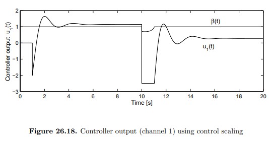
(ii) Input scaling When the idea shown in Figure 26.12 is applied to our example, the control output u_{1}(t) is automatically adjusted, as shown in Figure 26.18. In this figure u_{1}(t) and η(t) are depicted. Note that 0 < β < 1, over the time interval when the control signal \hat{u_{1}} (t) is beyond the saturation bound (in this example, −2.5).
However, a rather disappointing result is observed regarding the plant outputs. They are shown in Figure 26.19. The SIMULINK schematic can be found in file mmawu.mdl.
The results shown in Figure 26.19 show a slight improvement over those obtained using the pure anti wind-up mechanism (i).
(iii) Error scaling When the error scaling strategy is applied to our example we obtain the results shown in Figure 26.20.
In the case shown in Figure 26.20, a value of 0.1 was chosen for τ. The results are remarkably better than those produced by the rest of the strategies treated sofar. The SIMULINK schematic can be found in file mmawe.mdl. Actually, full dynamic decoupling is essentially retained here – the small coupling evident in Figure 26.20 is due to the implementation of the error scaling via a (fast) dynamical system.