Question 14.CS.10C: Design of a Return Spring for a Cam-Follower Arm Problem Des...
Design of a Return Spring for a Cam-Follower Arm
Problem Design an extension spring for the cam-follower arm in Figure 14-36 based on the loadings defined in Case Study 10A (p. 532).
Given The spring rate is 25 lb/in with a preload of 25 lb. The spring’s dynamic deflection is 1.5 in.
Assumptions The spring operates in an oil bath whose temperature is below 250°F. Infinite life is required. Use ASTM A228 music wire and standard loops on each end.

Learn more on how we answer questions.
See Figure 14-36.
1 Assume an 0.177-in trial wire diameter from the available sizes in Table 14-2 (p. 791). Assume a spring index of C = 8 and calculate the mean coil diameter D from equation 14.5 (p. 797).
C=\frac{D}{d} (14.5)
D=C d=8(0.177)=1.42 \text { in } (a)
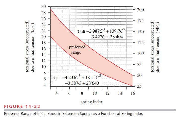
2 Use the assumed value of C to find an appropriate value of initial coil stress \tau _{i} from equations 14.21 (p. 821) as the average value of the functions that bracket the acceptable range of spring preloads in Figure 14-22 (p. 822):
k=\frac{F-F_i}{y}=\frac{d^4 G}{8 D^3 N_a} (14.21)
\begin{aligned} \tau_{i_1} & \cong-4.231 C^3+181.5 C^2-3387 C+28640 \\ &=-4.231(8)^3+181.5(8)^2-3387(8)+28640=10994 psi \end{aligned} (b)
\begin{aligned} \tau_{i_2} & \cong-2.987 C^3+139.7 C^2-3427 C+38404 \\ &=-2.987(8)^3+139.7(8)^2-3427(8)+38404=18399 psi \end{aligned} (c)
\tau_i \cong \frac{\tau_{i_1}+\tau_{i_2}}{2}=\frac{10994+18399}{2}=14697 psi (d)
3 Find the direct shear factor:
K_s=1+\frac{0.5}{C}=1+\frac{0.5}{8}=1.0625 (e)
4 Substitute K_{s} from step 3 and the value of \tau _{i} from equation (d) of step 2 for \tau _{max} in equation 14.8b (p. 798) to find the corresponding initial coil-tension force F_{i}:
\begin{aligned} \tau_{\max } &=\frac{8 F C}{\pi d^2}+\frac{4 F}{\pi d^2}=\frac{8 F C+4 F}{\pi d^2} \\ &=\frac{8 F C}{\pi d^2}\left\lgroup 1+\frac{1}{2 C} \right\rgroup =\frac{8 F D}{\pi d^3}\left\lgroup 1+\frac{0.5}{C} \right\rgroup \\ \tau_{\max } &=K_s \frac{8 F D}{\pi d^3} \quad \quad \text { where } K_s=\left\lgroup 1+\frac{0.5}{C} \right\rgroup \end{aligned} (14.8b)
F_i=\frac{\pi d^3 \tau_i}{8 K_s D}=\frac{\pi(0.177)^3(14697)}{8(1.0625)(1.416)}=21.272 lb (f)
Check that this force is less than the required 25-lb minimum applied force F_{min}, which in this case, it is. Any force smaller than F_{i} in the spring will not deflect it.
5 Find the maximum force from the given rate and deflection and use them to find the mean and alternating forces from equation 14.16a (p. 812):
\begin{array}{l} F_a=\frac{F_{\max }-F_{\min }}{2} \\ F_m=\frac{F_{\max }+F_{\min }}{2} \end{array} (14.16a)
\begin{aligned} F_{\max } &=F_{\min }+k y=25+25(1.5)=62.5 lb \\ F_a &=\frac{F_{\max }-F_{\min }}{2}=\frac{62.5-25}{2}=18.75 lb \\ F_m &=\frac{F_{\max }+F_{\min }}{2}=\frac{62.5+25}{2}=43.75 lb \end{aligned} (g)
6 Use the direct shear factor K_{s} and previously assumed values to find the minimum stress \tau _{min} and the mean stress \tau _{m}:
\begin{aligned} \tau_{\min } &=K_s \frac{8 F_{\min } D}{\pi d^3}=1.0625 \frac{8(25)(1.416)}{\pi(0.177)^3}=17272 psi \\ \tau_m &=K_s \frac{8 F_m D}{\pi d^3}=1.0625 \frac{8(43.75)(1.416)}{\pi(0.177)^3}=30227 psi \end{aligned} (h)
7 Find the Wahl factor K_{w} and use it to calculate the alternating shear stress in the coil.
K_w=\frac{4 C-1}{4 C-4}+\frac{0.615}{C}=\frac{4(8)-1}{4(8)-4}+\frac{0.615}{8}=1.184 (i)
\tau_a=K_w \frac{8 F_a D}{\pi d^3}=1.184 \frac{8(18.75)(1.416)}{\pi(0.177)^3}=14436 \text { psi } (j)
8 Find the ultimate tensile strength of this music-wire material from equation 14.3 and Table 14-4 (p. 792) and use it to find the ultimate shear strength from equation 14.4 (p. 793) and the torsional yield strength for the coil body from Table 14-12 (p. 824), assuming no set removal.
S_{u t} \cong A d^b (14.3)
S_{u s} \cong 0.67 S_{u t} (14.4)
\begin{array}{l} S_{u t}=A d^b=184649(0.177)^{-0.1625}=244653 psi \\ S_{u s}=0.67 S_{u t}=163918 psi \end{array} (k)
S_{y s}=0.45 S_{u t}=0.45(244653)=110094 psi (l)
9 Find the wire endurance limit for unpeened springs from equation 14.13 (p. 804) and convert it to a fully reversed endurance strength with equation 14.18b (p. 814).
\begin{array}{l} S_{e w} \cong 45.0 kpsi (310 MPa ) \quad \text {for unpeened springs }\\ S_{e w} \cong 67.5 kpsi (465 MPa ) \quad \text {for peened springs} \end{array} (14.13)
S_{e s}=0.5 \frac{S_{e w} S_{u s}}{S_{u s}-0.5 S_{e w}} (14.18b)
S_{e w}=45000 psi (m)
S_{e s}=0.5 \frac{S_{e w} S_{u s}}{S_{u s}-0.5 S_{e w}}=0.5 \frac{45000(163918)}{163918-0.5(45000)}=26080 psi (n)
10 The fatigue safety factor for the coils in torsion is calculated from equation 14.18a (p. 814).
N_{f_s}=\frac{S_{e s}\left(S_{u s}-\tau_i\right)}{S_{e s}\left(\tau_m-\tau_i\right)+S_{u s} \tau_a} (14.18a)
\begin{aligned} N_{f_s} &=\frac{S_{e s}\left(S_{u s}-\tau_{\min }\right)}{S_{e s}\left(\tau_m-\tau_{\min }\right)+S_{u s} \tau_a} \\ &=\frac{26080(163918-17272)}{26080(30227-17272)+163918(14436)}=1.4 \end{aligned} (o)
Note that the minimum stress due to force F_{min} is used in this calculation, not the coil-winding stress from equation (d).
11 The stresses in the end hooks also need to be determined. The bending stresses in the hook at point A in Figure 14-23 (repeated here) are found from equation 14.24 (p. 823):
\sigma_A=K_b \frac{16 D F}{\pi d^3}+\frac{4 F}{\pi d^2} (14.24a)
K_b=\frac{4 C_1^2-C_1-1}{4 C_1\left(C_1-1\right)} (14.24b)
C_1=\frac{2 R_1}{d} (14.24c)
\begin{array}{c} C_1=\frac{2 R_1}{d}=\frac{2 D}{2 d}=C=8 \\ K_b=\frac{4 C_1^2-C_1-1}{4 C_1\left(C_1-1\right)}=\frac{4(8)^2-8-1}{4(8)(8-1)}=1.103 \end{array} (p)
\begin{array}{l} \sigma_a=K_b \frac{16 D F_a}{\pi d^3}+\frac{4 F_a}{\pi d^2}=1.103 \frac{16(1.416)(18.75)}{\pi(0.177)^3}+\frac{4(18.75)}{\pi(0.177)^2}=27650 psi \\ \sigma_m=K_b \frac{16 D F_m}{\pi d^3}+\frac{4 F_m}{\pi d^2}=1.103 \frac{16(1.416)(43.75)}{\pi(0.177)^3}+\frac{4(43.75)}{\pi(0.177)^2}=64517 psi \end{array} (q)
\sigma_{\min }=K_b \frac{16 D F_{\min }}{\pi d^3}+\frac{4 F_{\min }}{\pi d^2}=1.103 \frac{16(1.416)(25)}{\pi(0.177)^3}+\frac{4(25)}{\pi(0.177)^2}=36867 psi (r)
12 Convert the torsional endurance strength to a tensile endurance strength with equation 14.4 (p. 793) and use it and the ultimate tensile strength in equation 14.18 (p. 814) to find a fatigue safety factor for the hook in bending:
N_{f_s}=\frac{S_{e s}\left(S_{u s}-\tau_i\right)}{S_{e s}\left(\tau_m-\tau_i\right)+S_{u s} \tau_a} (14.18a)
S_{e s}=0.5 \frac{S_{e w} S_{u s}}{S_{u s}-0.5 S_{e w}} (14.18b)
S_{u s} \cong 0.67 S_{u t} (14.4)
\begin{aligned} S_e &=\frac{S_{e s}}{0.67}=\frac{26080}{0.67}=38925 psi \\ N_{f_b} &=\frac{S_e\left(S_{u t}-\sigma_{\min }\right)}{S_e\left(\sigma_m-\sigma_{\min }\right)+S_{u t} \sigma_a} \\ &=\frac{38925(244633-38867)}{38925(64517-38867)+244633(27650)}=1.0 \end{aligned} (s)
13 Find the torsional stresses at point B of the hook in Figure 14-23 using equation 14.25 (p. 823) and an assumed value of C_{2} = 5.
\tau_B=K_{w_2} \frac{8 D F}{\pi d^3} (14.25a)
K_{W_2}=\frac{4 C_2-1}{4 C_2-4} (14.25b)
C_2=\frac{2 R_2}{d} (14.25c)
\begin{aligned} R_2 &=\frac{C_2 d}{2}=\frac{5(0.177)}{2}=0.443 \text { in } \\ K_{w_2} &=\frac{4 C_2-1}{4 C_2-4}=\frac{4(5)-1}{4(5)-4}=1.188 \end{aligned} (t)
\begin{array}{l} \tau_{B_a}=K_{w_2} \frac{8 D F_a}{\pi d^3}=1.188 \frac{8(1.416) 18.75}{\pi(0.177)^3}=14478 psi \\ \tau_{B_m}=K_{w_2} \frac{8 D F_m}{\pi d^3}=1.188 \frac{8(1.416) 43.75}{\pi(0.177)^3}=33783 psi \\ \tau_{B_{\min }}=K_{w_2} \frac{8 D F_{\min }}{\pi d^3}=1.188 \frac{8(1.416) 25}{\pi(0.177)^3}=19304 psi \end{array} (u)
14 The fatigue safety factor for the hook in torsion is calculated from equation 14.18a (p. 814).
N_{f_s}=\frac{S_{e s}\left(S_{u s}-\tau_i\right)}{S_{e s}\left(\tau_m-\tau_i\right)+S_{u s} \tau_a} (14.18a)
\begin{aligned} N_{f_s} &=\frac{S_{e s}\left(S_{u s}-\tau_{\min }\right)}{S_{e s}\left(\tau_m-\tau_{\min }\right)+S_{u s} \tau_a} \\ &=\frac{26080(163918-19304)}{26080(33783-19304)+163918(14478)}=1.4 \end{aligned} (v)
Two of these safety factors are acceptable. The safety of the hook in bending is low.
15 To get the specified spring rate, the number of active coils must satisfy equation 14.7 (p. 797):
k=\frac{F}{y}=\frac{d^4 G}{8 D^3 N_a} (14.7)
k=\frac{d^4 G}{8 D^3 N_a} \quad \text { or } \quad N_a=\frac{d^4 G}{8 D^3 k}=\frac{(0.177)^4 11.5 E 6}{8(1.416)^3(25)}=19.88 \cong 20 (w)
Note that we round it to the nearest 1/4 coil, as the manufacturing tolerance cannot achieve better than that accuracy. This makes the actual spring rate k = 24.8 lb/in.
16 The total number of coils in the body and the body length are
\begin{array}{l} N_t=N_a+1=20+1=21 \\ L_b=N_t d=21(0.177)=3.72 \text { in } \end{array} (x)
17 The length of a standard loop is equal to the coil inside diameter. The free length is
L_f=L_b+2 L_{\text {hook }}=3.72+2(1.24)=6.2 \text { in } (y)
18 The maximum deflection and spring length at that deflection are
\begin{array}{l} y_{\max }=\frac{F_{\max }-F_{\text {initial }}}{k}=\frac{62.5-21.27}{25}=1.65 \text { in } \\ L_{\max }=L_f+y_{\max }=6.2+1.65=7.85 \text { in } \end{array} (z)
This length is within the maximum cam diameter so is acceptable.
19 The natural frequency of this spring is found from equation 14.26 (p. 823) and is
f_n=\frac{2}{\pi N_a} \frac{d}{D^2} \sqrt{\frac{G g}{32 \gamma}} \quad Hz (14.26)
f_n=\frac{2}{\pi N_a} \frac{d}{D^2} \sqrt{\frac{G g}{32 \gamma}}=\frac{2(0.177)}{\pi(20)(1.416)^2} \sqrt{\frac{11.5 E 6(386)}{32(0.285)}}=62 Hz =3720 rpm (aa)
The ratio between the natural frequency and the forcing frequency is
\frac{3720}{180}=20.7 (ab)
which is sufficiently high.
20 The design specification for this A228 wire spring is
d=0.177 \text { in } \quad O D=1.593 \text { in } \quad N_t=21 \quad L_f=6.2 \text { in } (ac)
21 This design is marginal, as the hook is predicted to be at failure in bending fatigue after about a million cycles of operation. If that is too short a life, then the design should be iterated again to improve it. Increasing the wire size to 0.192 in and the spring index to 8.5 will raise all the safety factors, with the hook in bending the lowest at 1.2.
22 Models CASE10C-1 and CASE10C-2 are on the CD-ROM. The -1 model is as shown in this example. The -2 model uses the changed parameters of step 21 to improve the design.
| Table 14-4 Coefficients and Exponents for Equation 14.3 Source: Reference 1 |
|||||||
| ASTM# | Material | Range | Exponent b |
Coefficient A | Correlation Factor | ||
| mm | in | MPa | psi | ||||
| A227 | Cold drawn | 0.5–16 | 0.020–0.625 | –0.182 2 | 1 753.3 | 141 040 | 0.998 |
| A228 | Music wire | 0.3–6 | 0.010–0.250 | –0.1625 | 2 153.5 | 184 649 | 0.9997 |
| A229 | Oil tempered | 0.5–16 | 0.020–0.625 | –0.183 3 | 1 831.2 | 146 780 | 0.999 |
| A232 | Chrome-v | 0.5–12 | 0.020–0.500 | –0.145 3 | 1 909.9 | 173 128 | 0.998 |
| A401 | Chrome-s. | 0.8–11 | 0.031–0.437 | –0.093 4 | 2 059.2 | 220 779 | 0.991 |
| Table 14-12 Maximum Torsional and Bending Yield Strengths S_{ys} and S_{y} for Helical Extension Springs in Static Applications No Set Removal and Low-Temperature Heat Treatment Applied. Source: Ref. 1 |
|||
| Material | Maximum Percent of Ultimate Tensile Strength | ||
| S_{ys} in Torsion | S_{y} in Bending | ||
| Body | End | End | |
| Cold-drawn carbon steel (e.g., A227, A228) | 45% | 40% | 75% |
| Hardened and tempered carbon and low-alloy steel (e.g., A229, A230, A232, A401) | 50 | 40 | 75 |
| Austenitic stainless steel and nonferrous alloys (e.g., A313, B134, B159, B197) | 35 | 30 | 55 |