Question 15.CS.8D: Design of the Headbolts for an Air Compressor Problem Design...
Design of the Headbolts for an Air Compressor
Problem Design a set of cap screws to attach the head to the cylinder in Figure 9-1 based on the loads defined in Case Study 8A (p. 526).
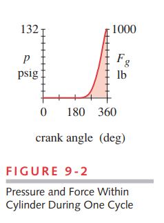
Given The compressor bore is 3.125-in diameter. The dynamic force acting on the head fluctuates from 0 to 1 000 lb each cycle from the 130- psi cylinder pressure. A 0.06-in-thick, unconfined copper-asbestos gasket covers the entire head-cylinder interface. The head thickness at the attachment points (exclusive of cooling fins) is 0.4 in.
Assumptions Infinite life. Use standard hex-head cap screws without washers. The operating temperature is less than 350°F. Use 99.9% reliability

Learn more on how we answer questions.
See Figures 9-1 and 9-2.
1 Choose a trial diameter d for the screws of 0.313 in. Use UNC threads to avoid stripping problems in the cast-aluminum cylinder. The trial fastener is then a 5/16-18 UNC-2A cap screw with rolled threads for fatigue resistance.
2 Choose a bolt circle and outside diameter based on the cylinder bore and the rule of thumb of at least 1.5d to 2d of distance between any screw and an edge. We will use 2d because of the need for sealing area against the cylinder pressure.
\begin{array}{l} d_{b c}=3.125+2(2)(0.313)=4.375 \text { in } \\ d_o=4.125+2(2)(0.313)=5.625 \text { in } \end{array} (a)
3 To get the recommended maximum of 6-screw-diameters spacing between bolts we will need about 8 screws equispaced around the bolt circle. Calculate the spacing between screws in units of screw diameters.
\Delta b=\frac{\pi D_p}{n_b d}=\frac{\pi(4.375)}{8(0.313)}=5.5 \text { bolt diameters } (b)
This is less than the maximum of 6 screw diameters so is acceptable. We will later calculate the gasket pressure to check for possible leakage.
4 Assume a trial screw length of 1.25 in. The head thickness of 0.40 in at the screw holes plus the 0.1-in gasket will leave 0.75 in of thread penetration into the cylinder’s tapped hole. This is > 2X the screw diameter (10 threads), which is the minimum recommended length for a steel screw in aluminum threads. For U.S. standard bolts up to 6-in long, the thread length is 2d + 0.25 = 0.875 in of this bolt’s length,^{[2]} which allows the desired penetration. The trial clamp length for the stiffness calculations is then 1.25 in, since the entire cap screw is engaged.
5 Try an SAE grade 7 screw preloaded to 70% of its proof strength. Table 15-6 (p. 882) shows the proof strength of this screw to be 105 kpsi. The tensile-stress area from equation 15-1 (p. 863) is 0.052 431 in². The required preload is then
A_t=\frac{\pi}{4}\left\lgroup \frac{d_p+d_r}{2} \right\rgroup ^2 (15.1a)
d_p=d-0.649519 / N \quad d_r=d-1.299038 / N (15.1b)
F_i=0.7 S_p A_t=0.7(105000)(0.052431)=3853.66 lb (c)
6 Find the joint aspect ratio and plate to screw modulus from equations 15.18a and b:
j=\frac{d}{l} (15.18a)
r=\frac{E_{\text {material }}}{E_{\text {bolt }}} (15.18b)
\begin{array}{l} j=\frac{d}{l}=\frac{0.313}{1.25}=0.25 \\ r=\frac{E_{\text {material }}}{E_{\text {bolt }}}=\frac{10.4 E 6}{30 E 6}=0.347 \end{array} (d)
7 Since this joint has the same material (aluminum) throughout, equation 15.19 is all that is needed to calculate the joint constant C_{ng} for the metal without the gasket. The parameters needed for the equation are found by interpolating for j = 0.25 in Table 15-8. They are: p_{0} = 0.653, p_{1} = –1.207, p_{2} = 1.103, and p_{3} = –0.383.
C_r=p_3 r^3+p_2 r^2+p_1 r+p_0 (15.19)
\begin{aligned} C_{n g} &=p_3 r^3+p_2 r^2+p_1 r+p_0 \\ &=-0.383(0.347)^3+1.103(0.347)^2-1.207(0.347)+0.653=0.351 \end{aligned} (e)
8 We can approximate the stiffness of the screw k_{b^{\prime}} with equation 15.17, then estimate
material stiffness k_{m} with no gasket by using equation 15.13c, given k_{b^{\prime}} and C_{ng}.
P_b=\frac{k_b}{k_m+k_b} P \\ \text {or} \quad P_b=C P \quad \text { where } \quad C=\frac{k_b}{k_m+k_b} (15.13c)
k_{b^{\prime}}=\left\lgroup 1+\frac{d}{l}\right\rgroup ^{-1} k_b \cong\left\lgroup 1+\frac{d}{l}\right\rgroup ^{-1} \frac{A_t A_b}{A_b l_t+A_t l_s} E_b (15.17)
\begin{aligned} \text {length of thread :} \quad l_{t h d} &=2 d+0.25=2(0.313)+0.25=0.875 \text { in } \\ \text {length of shank :} \quad l_s &=l_{b o l t}-l_{\text {thd }}=1.25-0.875=0.375 \text { in } \\ \text {length of clamped thread :} \quad l_t &=l-l_s=1.25-0.375=0.875 \text { in } \end{aligned}
\begin{aligned} k_{b^{\prime}} & \cong\left\lgroup 1+\frac{d}{l} \right\rgroup ^{-1} \frac{A_t A_b}{A_b l_t+A_t l_s} E_b \\ k_{b^{\prime}} & \cong\left\lgroup 1+\frac{0.313}{1.25} \right\rgroup ^{-1} \frac{0.052(0.077)}{0.077(0.875)+0.052(0.375)} 30 E 6=1.112 E 6 lb / in \end{aligned}
C_{n g}=\frac{k_{b^{\prime}}}{k_{m_1}+k_{b^{\prime}}} \Rightarrow k_{m_1}=k_{b^{\prime}} \frac{1-C_{n g}}{C_{n g}}=1.112 E 6\left\lgroup\frac{1-0.351}{0.351} \right\rgroup =2.060 E 6 lb / in (f)
9 Now consider the gasket. The area of the unconfined gasket subjected to the clamp force can be assumed to be that of one “bolt’s worth” of the total clamped area which extends from the outside diameter of the cylinder head to the bore:
A_{\text {total }}=\frac{\pi}{4}\left\lgroup D_o^2-D_1^2\right\rgroup=\frac{\pi}{4}\left\lgroup 5.625^2-3.125^2\right\rgroup \cong 17.18 in ^2 (g)
Dividing by the number of bolts and subtracting the screw hole area gives the area of the clamped gasket around any one screw as:
A_g=\frac{A_{\text {total }}}{n_b}-\frac{\pi}{4} d^2=\frac{17.18}{8}-\frac{\pi}{4} 0.313^2=2.071 in ^2 (h)
10 The stiffness of this piece of gasket is then
k_{m_2}=\frac{A_g E_g}{l_g}=\frac{2.071(13.5 E 6)}{0.06} \cong 4.659 E 8 lb / in (i)
The modulus of elasticity of the gasket material is found in Table 15-10 (p. 900).
11 The material and gasket stiffness combine according to equation 14.2b (p. 787). The combined stiffness of the gasketed joint is then
\frac{1}{k_{\text {total }}}=\frac{1}{k_1}+\frac{1}{k_2}+\frac{1}{k_3}+\ldots+\frac{1}{k_n} (14.2b)
\begin{array}{l} k_{m_g}=\frac{1}{\frac{1}{k_{m_1}}+\frac{1}{k_{m_2}}}=\frac{1}{\frac{1}{2.060 E 6}+\frac{1}{4.659 E 8}} \\ k_{m_g}=2.051 E 6 lb / \text { in } \end{array} (j)
Note that the combined stiffness in this case is dominated by the aluminum because the copper-asbestos gasket is stiffer.
12 The joint constant with the unconfined gasket is
\begin{array}{c} C=\frac{k_{b^{\prime}}}{k_{m_g}+k_{b^{\prime}}}=\frac{1.112 E 6}{2.051 E 6+1.112 E 6} \cong 0.352 \\ \text {and} \quad (1-C)=0.648 \end{array} (k)
13 The 1 000-lb load is assumed to be divided equally among the 8 bolts at 125 lb each. The portions of the applied load felt by each screw and material (Eq. 15.13, p. 886) are:
\Delta \delta=\frac{P_b}{k_b}=\frac{P_m}{k_m} (15.13a)
P_b=\frac{k_b}{k_m} P_m (15.13b)
P_b=\frac{k_b}{k_m+k_b} P \\ \text {or} \quad P_b=C P \quad \text { where } \quad C=\frac{k_b}{k_m+k_b} (15.13c)
P_m=\frac{k_m}{k_b+k_m} P=(1-C) P (15.13d)
\begin{array}{l} P_b=C P=0.352(125) \cong 43.95 lb \\ P_m=(1-C) P=0.614(125) \cong 81.05 lb \end{array} (l)
14 The resulting peak loads in screw and material are
\begin{array}{l} F_b=F_i+P_b=3853.66+43.95=3897.61 lb \\ F_m=F_i-P_m=3853.66-81.05=3772.61 lb \end{array} (m)
15 The alternating and mean components of force on the screw are
\begin{array}{l} F_{a l t}=\frac{F_b-F_i}{2}=\frac{3897.61-3853.66}{2} \cong 21.98 lb\\ F_{\text {mean }}=\frac{F_b+F_i}{2}=\frac{3897.61+3853.66}{2} \cong 3875.63 lb \end{array} (n)
16 The nominal mean and alternating stresses in the screw are
\begin{array}{l} \sigma_{a_{\text {nom }}}=\frac{F_{\text {alt }}}{A_t}=\frac{21.98}{0.052431} \cong 419.2 psi \\ \sigma_{m_{\text {nom }}}=\frac{F_{\text {mean }}}{A_t}=\frac{3875.63}{0.052431} \cong 73919 psi \end{array} (o)
17 The fatigue stress-concentration factor for this diameter thread is found from equation 15.15c and the mean stress-concentration factor K_{fm} is found from equation 6.17 (p. 364).
\begin{array}{ll} \quad K_f=5.7+0.6812 d & d \text { in inches } \\ \text {or} \\ \quad K_f=5.7+0.02682 d & d \text { in mm } \end{array} (15.15c)
\begin{array}{ll} \text {if} K_f\left|\sigma_{\max _{\text {nom }}}\right|<S_y \text { then : } & K_{f m}=K_f \\ \text {if} K_f\left|\sigma_{\max _{\text {nom }}}\right|>S_y \text { then : } & K_{f m}=\frac{S_y-K_f \sigma_{a_{\text {nom }}}}{\left|\sigma_{m_{\text {nom }}}\right|} \\ \text {if} K_f\left|\sigma_{\max _{\text {nom }}}-\sigma_{\min _{\text {nom }}}\right|>2 S_y \text { then: } & K_{f m}=0 \end{array} (6.17)
\begin{array}{l} K_f=5.7+0.6812 d=5.7+0.6812(0.313)=5.9 \\ \text { if } K_f\left|\sigma_{\max _{\text {nom }}}\right|>S_y \text { then : }\qquad \quad K_{f m}=\frac{S_y-K_f \sigma_{a_{\text {nom }}}}{\left|\sigma_{m_{\text {nom }}}\right|} \\ K_f\left|\sigma_{\max _{\text {nom }}}\right|=K_f\left|\sigma_{a_{\text {nom }}}+\sigma_{m_{\text {nom }}}\right|=5.9|460.2+73960|=440039 psi \\ 440039 psi >S_y=115000 psi \end{array}
K_{f m}=\frac{S_y-K_f \sigma_{a_{\text {nom }}}}{\left|\sigma_{m_{\text {nom }}}\right|}=\frac{115000-5.9(460.2)}{73960}=1.52 (p)
18 The local mean and alternating stresses in the screw are
\begin{array}{l} \sigma_a=K_f \frac{F_{\text {alt }}}{A_t}=5.9 \frac{21.98}{0.052431} \cong 2478 psi \\ \sigma_m=K_{f m} \frac{F_{\text {mean }}}{A_t}=1.52 \frac{3875.63}{0.052431} \cong 112522 psi \end{array} (q)
19 The stresses at the initial preload and at the maximum screw force are
\begin{aligned} \sigma_i &=K_{f m} \frac{F_i}{A_t}=1.52 \frac{3853.66}{0.052431} \cong 111883 psi \\ \sigma_b &=K_{f m} \frac{F_b}{A_t}=1.52 \frac{3897.61}{0.052431}=113160 psi \end{aligned} (r)
20 The endurance strength for this material is found using the methods of Section 6.6 (p. 327):
S_{e^{\prime}}=0.5 S_{u t}=0.5(133000)=66500 psi (s)
\begin{aligned} S_e &=C_{\text {load }} C_{\text {size }} C_{\text {surf }} C_{\text {temp }} C_{\text {reliab }} S_{e^\prime} \\ &=0.70(.995)(0.739)(1)(0.753)(66500)=25778 psi \end{aligned} (t)
where the strength-reduction factors are taken from the tables and formulas in Section 6.6 for, respectively, axial loading, the screw size, a machined finish, room temperature, and 99.9% reliability.
21 The corrected endurance strength and the ultimate tensile strength are used in equation 15.16 (p. 891) to find the fatigue safety factor from the Goodman line.
N_f=\frac{S_e\left(S_{u t}-\sigma_i\right)}{S_e\left(\sigma_m-\sigma_i\right)+S_{u t} \sigma_a} (15.16)
\begin{aligned} N_f &=\frac{S_e\left(S_{u t}-\sigma_i\right)}{S_e\left(\sigma_m-\sigma_i\right)+S_{u t} \sigma_a} \\ &=\frac{25778(133000-111883)}{25778(112522-111883)+133000(2478)} \cong 1.6 \end{aligned} (u)
22 The static screw stress after initial local yielding and the yielding safety factor are:
\sigma_s=\frac{F_{b o l t}}{A_t}=\frac{3897.61}{0.052431}=74338 psi \quad N_y=\frac{S_y}{\sigma_b}=\frac{115000}{74338} \cong 1.5 (v)
23 The safety factor against joint separation is found from equation 15.14d (p. 887).
N_{\text {separation }}=\frac{P_0}{P}=\frac{F_i}{P(1-C)} (15.14d)
N_{\text {separation }}=\frac{F_i}{P(1-C)}=\frac{3853.66}{125(1-0.352)} \cong 47 (w)
24 The joint will leak unless the clamping forces are sufficient to create more pressure at the gasket than exists in the cylinder. The minimum clamping pressure can be found from the total area of the gasketed joint and the minimum clamping force F_{m}.
\begin{array}{c} p_{a v g}=\frac{F_m}{A_j}=\frac{4 F_m}{\pi\left(D_o^2-D_i^2\right)-n_b A_b}=\frac{4(3772.6)}{\pi\left(5.625^2-3.125^2\right)-8(0.077)} \cong 228 psi \\ N_{\text {leak }}=\frac{p_{\text {avg }}}{p_{c y l}}=\frac{228}{130} \cong 1.7 \end{array} (x)
This ratio of clamp pressure vs. cylinder pressure makes the screw spacing acceptable.
25 The torque required to obtain the preload of 3853.66 lb found in step 5 is:
T_i \cong 0.21 F_i d=0.21(3853.66)(0.313) \cong 253 lb -\text { in } (y)
26 This design uses eight 5/16-18 UNC-2A, grade 7 hex-head cap screws, 1.25 in long, preloaded to 70% of proof strength and equispaced on a 4.375-in-dia bolt circle. This design has a safety factor against leakage of 1.7, a fatigue safety factor of 1.6, and can stand 47 times the operating pressure before joint separation will occur. These safety factors are acceptable. The files CASE8D can be found on the CD-ROM.
| Table 15-6 SAE Specifications and Strengths for Steel Bolts | |||||
| SAE Grade Number | Size Range Outside Diameter (in) | Minimum Proof Strength (kpsi) | Minimum Yield Strength (kpsi) | Minimum Tensile Strength (kpsi) | Material |
| 1 | 0.25–1.5 | 33 | 36 | 60 | low or medium carbon |
| 2 | 0.25–0.75 | 55 | 57 | 74 | low or medium carbon |
| 2 | 0.875–1.5 | 33 | 36 | 60 | low or medium carbon |
| 4 | 0.25–1.5 | 65 | 100 | 115 | medium carbon, cold drawn |
| 5 | 0.25–1.0 | 85 | 92 | 120 | medium carbon, Q&T* |
| 5 | 1.125–1.5 | 74 | 81 | 105 | medium carbon, Q&T |
| 5.2 | 0.25–1.0 | 85 | 92 | 120 | low-carbon martensite, Q&T |
| 7 | 0.25–1.5 | 105 | 115 | 133 | medium-carbon alloy, Q&T |
| 8 | 0.25–1.5 | 120 | 130 | 150 | medium-carbon alloy, Q&T |
| 8.2 | 0.25–1.0 | 120 | 130 | 150 | low-carbon martensite, Q&T |
| * Quenched and Tempered. | |||||
| Table 15-8 Parameters for Equation 15.19 ^{[15]} | ||||
| j | p_{0} | p_{1} | p_{2} | p_{3} |
| 0.10 | 0.4389 | –0.9197 | 0.8901 | –0.3187 |
| 0.20 | 0.6118 | –1.1715 | 1.0875 | –0.3806 |
| 0.30 | 0.6932 | –1.2426 | 1.1177 | –0.3845 |
| 0.40 | 0.7351 | –1.2612 | 1.1111 | –0.3779 |
| 0.50 | 0.7580 | –1.2632 | 1.0979 | –0.3708 |
| 0.60 | 0.7709 | –1.2600 | 1.0851 | –0.3647 |
| 0.70 | 0.7773 | –1.2543 | 1.0735 | –0.3595 |
| 0.80 | 0.7800 | –1.2503 | 1.0672 | –0.3571 |
| 0.90 | 0.7797 | –1.2458 | 1.0620 | –0.3552 |
| 1.00 | 0.7774 | –1.2413 | 1.0577 | –0.3537 |
| 1.25 | 0.7667 | –1.2333 | 1.0548 | –0.3535 |
| 1.50 | 0.7518 | –1.2264 | 1.0554 | –0.3550 |
| 1.75 | 0.7350 | –1.2202 | 1.0581 | –0.3574 |
| 2.00 | 0.7175 | –1.2133 | 1.0604 | –0.3596 |
| Table 15-10 Young’s Modulus for Some Gasket Materials Source: Reference 12 with permission of McGraw-Hill, Inc., New York |
||
| Material | Modulus of Elasticity | |
| psi | MPa | |
| Cork | 12.5E3 | 86 |
| Compressed asbestos | 70E3 | 480 |
| Copper-asbestos | 13.5E6 | 93E3 |
| Copper (pure) | 17.5E6 | 121E3 |
| Plain rubber | 10E3 | 69 |
| Spiral wound | 41E3 | 280 |
| Teflon | 35E3 | 240 |
| Vegetable fiber | 17E3 | 120 |