Question 13.8: FINDING THE TRANSIENT RESPONSE OF AN RMS CIRCUIT The rms val...
FINDING THE TRANSIENT RESPONSE OF AN RMS CIRCUIT
The rms value of an input signal v_{in} = sin(120πt) is to be fed to a load resistance R_{L} = 1 GΩ. This is shown in Figure 13.30(a). Use PSpice to plot the transient response of the input and output voltages for a duration of 0 to 33.33 msec in steps of 10 μsec.

Learn more on how we answer questions.
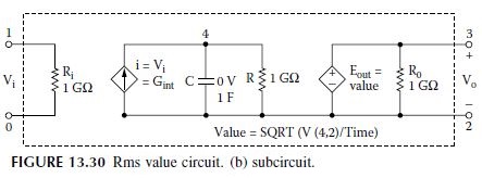
The rms value is determined by the RC circuit of Figure 13.30(b). The input frequency is f = 60 Hz.
The PSpice schematic is shown in Figure 13.31(a) for an rms circuit. Figure 13.31(b)
shows an implementation with an ABM integrator.
The listing of the circuit file is as follows:
Example 13.8 RMS circuit
| SOURCE VIN 1 0 SIN (0 1V 60HZ) CIRCUIT RL 2 0 1G * Calling subcircuit RMS: R 4 2 1G ANALYSIS .TRAN 10US 33.33MS UIC ; Use initial condition in transient analysis .END |
The plots of the transient response for the input and output voltages are shown in
Figure 13.32. The rms value of a sine wave with 1 V peak is 1 V/\sqrt {2} = 0.707 V.