Question 10.3: Load-Line Analysis of a Zener-Diode Voltage Regulator The vo...
Load-Line Analysis of a Zener-Diode Voltage Regulator
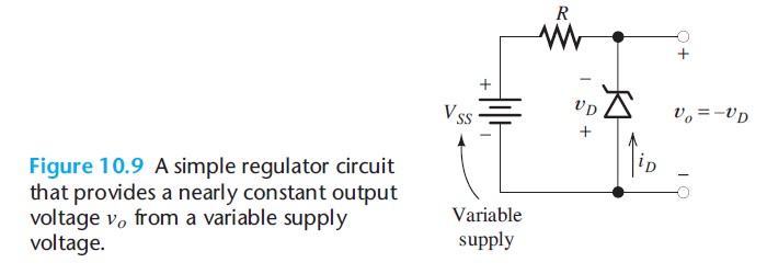
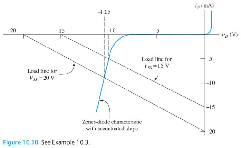
The voltage-regulator circuit of Figure 10.9 has R = 1 kΩ and uses a Zener diode having the characteristic shown in Figure 10.10. Find the output voltage for VSS = 15V. Repeat for VSS = 20 V.
Learn more on how we answer questions.
The load lines for both values of VSS are shown in Figure 10.10. The output voltages are determined from the points where the load lines intersect the diode characteristic. The output voltages are found to be vo = 10.0 V for VSS = 15V and vo = 10.5V for VSS = 20V.Thus, a 5-V change in the supply voltage results in only a 0.5-V change in the regulated output voltage.
Actual Zener diodes are capable of much better performance than this. The slope of the characteristic has been accentuated in Figure 10.10 for clarity actual Zener diodes have a more nearly vertical slope in breakdown.