Question 5.EC.1: Hall Effect and Magnetoresistivity Effect Apparatus and mate......
Hall Effect and Magnetoresistivity Effect
Apparatus and materials
(1) Three digital multimeters.
(2) A Hall sensor with four pins MNPQ (M in black wire, N yellow wire, P red wire, Q green wire), fixed on a printed circuit, a pair of conductors leading to M, N; another pair of conductors leading to P, Q.
(3) A permanent magnet in the shape of a disk, of radius r = 14 mm, of thickness t = 4 mm. The magnetization is perpendicular to the surface of the disk. The value B_{0} (in Tesla) of the magnetic field at the surface of the magnet is written on its surface.
During the experiment, keep the magnet far away from the Hall sensor
whenever you do not use it.
(4) A coil of N turns is wound on a core having the shape of a toroid, made of a ferromagnetic material. The average radius of the core is ρ = 25 mm. The toroid has a gap of width d = 3 mm.
(5) A box with two independent 1. 5 V dry cells. The cell connected in series to a 10 kΩ, variable resistor, called battery 1, is used to supply the current to the Hall sensor. The second cell, called battery 2, is used to supply the current to the coil only during the measurement.
(6) A protractor with a small hole at its center.
(7) A piece of plexiglass with a small needle fixed on it.
(8) A holder for the printed circuit with the Hall sensor.
(9) A small piece of plastic used to fix the sensor on the needle.
C1O) Conductors with negligible resistance.
(11) Graph papers.
Experiment
I. Introduction
The magnetoresistivity effect and the Hall effect. Consider a conductor sample in the shape of a parallelopiped of length a, width b and thickness c (see Fig. 5 – 7). The current I flows along the direction of a. If the sample is placed in a magnetic field B, The magnetic field affects the resistance R of the sample. This effect is called magneto -resistivity effect (MRE) . Let ΔR the increase of the resistance R of the sample, R_{0} – the value of R In the absence of magnetic field, then the magnitude of the MRE is defined by the ratIo {\frac{\Delta R}{R_{0}}}.
Assume that the applied magnetic field is uniform and the magnetic induction vector B is parallel to the top face of the sample as shown in Fig.S – 7. If the charge carriers in the sample are electrons, the Lorentz force will bend them upward, and the top face of the sample will be charged negatively. This effect is called the Hall effect. The voltage appearing between electrodes M (on the top face) and N (on the bottom face) is called the Hall voltage. This can be measured by use of a voltmeter.
The potential difference measured between the electrodes M and N is given by
U_{M N}=U_{\mathrm{H}}+V_{M N}\,, (1)
where U_{H} is the Hall voltage, V_{MN} is the potential difference in the absence of magnetic field due to some undesired effects (the electrodes M and N being not exactly opposite to each other, etc.).
Normally, the Hall voltage U_{H} is proportional to IB • sin θ, and the magnitude of the MRE is proportional to B² sin² θ , where e is the angle between vector B and the current direction. But when the sample has a non regular shape, the dependence of U_{H} and {\frac{\Delta R}{R}}. on B sin θ may be more complicated.
The Hall effect is used to fabricate a device for measuring the magnetic field. This device is called the Hall sensor. For Hall sensor, the expression of U_{H} is given by
U_{\mathrm{H}}=\alpha\cdot I\cdot B\cdot\sin\theta, (2)
where α is, by definition, the sensitivity of the Hall sensor.
II. The measuring sample
The measuring sample in this experiment is a commercial Hall sensor. It consists of a small thin semiconductor plate covered with plastic, with 4 ohmic electrodes, leading to the pins M, N, p, Q
(see Fig.5 – 8). It is used in this experiment to study both the MRE and the Hall effect.
Place the sensor in the magnetic field and use an ohmmeter to mesure the resistance between pins M and N, we can deduce the magnitude of the MRE. Set a current (I ~ 1 mA) flowing from P to Q, we can study the Hall effect by measuring the voltage between M and N with a milivoltmeter.
III. Experiment
(1) Determination of the sensitivity α of the Hall sensor.
Set the current through the sensor I~1 mA. Keep the distance between the sensor and the centre of the surface of the magnet y = 2 cm. Adjust the orientation of magnet for obtaining maximal value of Hall voltage. Measure the Hall voltage with some values of I and determine the sensitivity α of the Hall sensor.
For a magnet having the shape of a disk of radius r, thickness t, the magnetic field at a point situated on its axis at a distance y from the center of the disk surface with y » t is given by the expression
B(y)=\frac{1}{2}B_{0}\Bigl[\frac{y+t}{\sqrt{(y+t)^{2}+r^{2}}}-\frac{y}{\sqrt{y^{2}+r^{2}}}\Bigr], (1)
where B_{0} is the magnetic induction at the surface of the magnet. The value of B_{0} is given on the surface of the magnet.
(2) Study of the dependence of U_{H} on angle θ between B and the current direction
Set the current through the sensor I ~ 1 mA. Keep the distance between the sensor and the centre of the surface of the magnet y = 2 em. Put the magnet on the protractor so that the plane of the magnet is perpendicular to the line connecting the sensor and centre of the magnet.
(a) Draw a sketch of the experimental arrangement.
(b) Tabulate the values of U_{H} for θ in the range of – 90° « θ « 90°.
(c) Verify the proportionality between U_{H} and sin θ by using a graph plotted in an appropriate way.
(3) Study of the dependence of \frac{\Delta R}{R} If on B, for B perpendicular to the sample plane.
The MRE is significant only at sufficiently strong magnetic field. So it is recommended to use a magnetic field as strong as possible.
(a) Draw a sketch of the experimental arrangement and explain the principle of the measurements.
(b) Perform measurements and tabulate the data.
(c) Assume that{\frac{\Delta R}{R}}\sim B^{k}, determine the value of k by using a graph plotted in an appropriate way. Estimate the maximal deviation of the obtained value of k.
(4) Determination of the relative permeability μ of the ferromagnetic materials of the core of the toroidal coil
Determine the relative permeability μ of the core material at the measured current intensity I by following this guidance step by step:
• Put the Hall sensor into the gap on the core.
• Connect the coil and an ammeter to battery 2. Use only the inputs
“COM” and “20 A” of the ammeter in this case.
• Measure the current I in the coil and the magnetic field B in the gap.
• Calculate the value of μ.
You can use the following relation:
\frac{B(2\pi\rho-d)}{\mu}+B d=4\pi10^{-7}N I.The average radius of the core p = 25 mm; N = number of turns; the width of the gap d = 3 mm.
Appendix
Instruction for the digital multimeter
(1) Press the Power On/Off button before use.
(2) When the multimeter is used as a milliammeter, the inlets are COM and A. Turn the Function Dial to DCA (2 m to 200 m) .
(3) When the multimeter is used as an ammeter, the inlets are COM and 20 A. Turn the Function Dial to DCA (20 m) .
(4) When the multimeter is used as a millivoltmeter, the inlets are COM and VΩ. Turn the Function Dial to DCV (200 m to 1000 m).
(5) When the multimeter is used as an ohmmeter, the inlets are COM and VΩ. Turn the Function Dial to 0 (200 m to 200 m).


Learn more on how we answer questions.
(1) Determination of the sensitivity a of the Hall sensor The current I_{H} supplied by battery 1 and flowing through the miliammeter and the sensor via the pins P and Q is maintained unchanged. Use the variable resistance to maintain I_{H} ~ 1 mA. The Hall voltage U_{H} is measured across the pins M and N with a milivoltmeter.
In the absence of a magnetic field, we obtain – 1. 3 mV < V_{MN} < 1. 3 mV.
Put the magnet on the protractor at a distance y = 2 cm = 2 × 10^{-2} m from the sensor.
Rotate the protractor to obtain the maximum value of U_{H} • We find the position of the magnet, in which the line joining the magnet and the sensor is perpendicular to the surface of the sensor. In this position of the magnet the axis is perpendicular to the surface of the sensor and B is perpendicular to the current I_{H} , and θ = 90°.
Measure U_{MN} and calculate the value of U_{H} : U_{H} = U_{MN} – V_{MN}. Calculate the value of B by using Eq. (1) .
Use the relation \alpha={\frac{U_{\mathrm{H}}}{\mathrm{IB}}} to calculate the value of α.
Repeat the measurement to obtain 4 – 5 different values of α, and calculate the mean value of α and the deviation Δα.
(2) Study the dependence of U_{H} on θ.
(a) Keeping y unchanged, y = 2 cm. By rotating the protractor, we change the angle θ between B and the current direction.
(b) At each angle θ , measure U_{H}(always with the same I_{H} ). Vary the angle in the range – 90° ≤ θ ≤ 90°.
Tabulate U_{H} versus θ.
For U_{H}= \gamma sin θ, then:
\ln{U_{\mathrm{H}}}=\ln\gamma+m\cdot\ln(\sin\theta) (2)
Plot In U_{H} versus In(sin θ), we get m and the error.
We find that the graph of In U_{H} versus ln(sin θ) is a straight line. From the graph we can deduce m = 1.
(3) Study the dependence of \frac{\Delta R}{R}on B.
The Hall sensor, with its sensitivity ex obtained from part (1), is used to measure the magnetic induction B. It serves to study the magnetoresistivity as well. Because the resistance between N and M does not change during the experiment (and equals about 350 Ω) we can study the dependence ΔR instead of\frac{\Delta R}{R}on B.
(a) Keep the axis of the magnet perpendicular to the surface of the sensor by the procedure described in part (1). Provide a current I = 1 mA to the Hall sensor and measure the intensity of the magnetic field (at the sensor).
Turn off the current, and switch the muItimeter from the milivoltmeter regime to the ohmmeter regime.
Measure the resistance between N and M and calculate the value of ΔR.
Vary the distance y from the sensor to the magnet from 2 cm to o. 6 cm and repeat the above measurement. Tabulate the values of \frac{\Delta R}{R} or ΔR versus B.
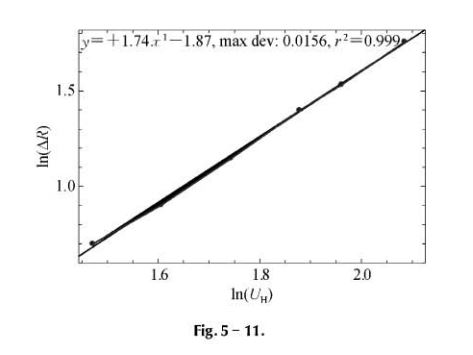
(b) Assuming\frac{\Delta R}{R}=\beta\cdot B^{k},we have
\mathrm{ln}\big(\frac{\Delta R}{R}\big)=\mathrm{ln}\,\beta+k\mathrm{ln}\,B. (1)
Plot In ( \frac{\Delta R}{R}) versus In B.
Draw a straight line passing as nearly the experimental points as possible. The slope of this line gives the value of k. One can find the value k~2. The deviation of k can be estimated from the graph by using eyeballing method.
The student may use the less square method to determine k and the error.
(4) Determination of the permeability μ of a ferromagnetic core in a toroidal coil.
Put the Hall sensor into the gap. Keep the current through the sensor constant, I = 1 mA The sensor is used to measure B in the gap.
Connect the coil to battery 2 via an ammeter. Note the value I_{C} of the current flowing in the coil. I_{C} varies from 3 to 4 amperes. Turn off immediately the current I_{C} after reading its value, to avoid the variation of the temperature of the sensor.
Count the number N of turns of the coil. From the values of U_{H} , α, determine B. From the values of B, \rho, d and N, using the relation:
\frac{B(\rho\!-\!d)}{\mu}+B d=4\pi\cdot 10^{-7}\cdot N\cdot I,we obtain the value of μ.