Question 15.1: A beam is to be made of steel that has an allowable bending ......
A beam is to be made of steel that has an allowable bending stress of \sigma_{\text {allow }}=24 \mathrm{ksi} and an allowable shear stress of \tau_{\text {allow }}=14.5 \mathrm{ksi}. Select an appropriate W shape that will carry the loading shown in Fig. 15-7a.

Learn more on how do we answer questions.
Shear and Moment Diagrams. The support reactions have been calculated, and the shear and moment diagrams are shown in Fig. 15-7b. From these diagrams, V_{\max }=30 \mathrm{kip} and M_{\max }=120 \mathrm{kip} \cdot \mathrm{ft}.
Bending Stress. The required section modulus for the beam is determined from the flexure formula,
S_{\text {req'd }}=\frac{M_{\text {max }}}{\sigma_{\text {allow }}}=\frac{120 \mathrm{kip} \cdot \mathrm{ft}(12 \mathrm{in} . / \mathrm{ft})}{24 \mathrm{kip} / \mathrm{in}^{2}}=60 \mathrm{in}^{3}
Using the table in Appendix B, the following beams are adequate:
\begin{array}{rl} \text { W18 } \times 40 & S=68.4 \mathrm{in}^3 \\ \text { W16 } \times 45 & S=72.7 \mathrm{in}^3 \\ \text { W14 } \times 43 & S=62.7 \mathrm{in}^3 \\ \text { W12 } \times 50 & S=64.7 \mathrm{in}^3 \\ \text { W10 } \times 54 & S=60.0 \mathrm{in}^3 \\ \text { W8 } \times 67 & S=60.4 \mathrm{in}^3 \end{array}
The beam having the least weight per foot is chosen,* i.e.,
W18 \times 40
Shear Stress. Since the beam is a wide-flange section, the average shear stress within the web will be considered. (See Example 12.3.) Here the web is assumed to extend from the very top to the very bottom of the beam. From Appendix B, for a W18 \times 40, d=17.90 in., t_{w}=0.315 \mathrm{in}. Thus,
\tau_{\text {avg }}=\frac{V_{\max }}{A_{w}}=\frac{30 \mathrm{kip}}{(17.90 \mathrm{in} .)(0.315 \mathrm{in} .)}=5.32 \mathrm{ksi}<14.5 \mathrm{ksi} \quad \text { OK }
Use a W18 \times 40.
*The additional moment caused by the weight of the beam, (0.040 \mathrm{kip} / \mathrm{ft})(18 \mathrm{ft})=0.720 \mathrm{kip}, will only slightly increase S_{\text {req'd. }}
Appendix B
GEOMETRIC PROPERTIES OF AN AREA AND VOLUME
| Centroid location | Centroid location | Area Moment of Inertia |
 |
 |
\begin{array}{c}{{I_{x}={\frac{1}{4}}\,r^{4}\left(\theta-{\frac{1}{2}}\sin2\theta\right)}}\\ {{I_{y}={\frac{1}{4}}\,r^{4}\left(\theta+{\frac{1}{2}}\sin2\theta\right)}}\end{array} |
 |
 |
\begin{array}{c}{{I_{x}={\frac{1}{16}}\pi r^{4}}}\\ {{I_{y}={\frac{1}{16}}\pi r^{4}}}\end{array} |
 |
 |
\begin{array}{c}{{I_{x}={\frac{1}{8}}\pi r^{4}}}\\ {{I_{y}={\frac{1}{8}}\pi r^{4}}}\end{array} |
 |
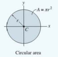 |
\begin{array}{c}{{I_{x}={\frac{1}{4}}\pi r^{4}}}\\ {{I_{y}={\frac{1}{4}}\pi r^{4}}}\end{array} |
 |
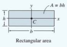 |
\begin{array}{c}{{I_{x}={\frac{1}{12}}b h^{3}}}\\ {{I_{y}={\frac{1}{12}}h b^{3}}}\end{array} |
 |
 |
I_{x}=\textstyle{\frac{1}{36}}b h^{3} |