Question 27.11: A uniform cantilever of length l has the doubly symmetrical ......
A uniform cantilever of length l has the doubly symmetrical cross-section shown in Fig. P.27.11. The section shape remains undistorted in its own plane after loading. Direct stresses in the cross-section are carried only in the concentrated longeron areas shown, and the wall thickness dimensions given relate only to shearing effects. All longerons have the same Young’s modulus E and all walls the same effective shear modulus G. The root of the cantilever is built in, warping being completely suppressed there, and a shearing force S is applied at the tip in the position indicated Derive an expression for the resultant end load in a corner longeron. Also calculate the resultant deflection of the tip, including the effects of both direct and shear strains.

Learn more on how do we answer questions.
This problem is similar to that of the six-boom beam analyzed in Section 27.4 (Fig. 27.11), and thus the top cover of the beam is subjected to the loads shown in Fig. S.27.11(a). From symmetry, the shear flow in the central panel of the cover is zero.
Considering the equilibrium of the element \delta z of the corner longeron (1) in Fig. S.27.11(b),
i.e.,
{\frac{\partial P_{1}}{\partial z}}=q-{\frac{S}{2h}} (i)
Now considering the equilibrium of the element \delta z of longeron 2 in Fig. S.27.11(c),
P_2+\frac{\partial P_2}{\partial z} \delta z-P_2+q \delta z=0which gives
{\frac{\partial P_{2}}{\partial z}}=-q (ii)
From the equilibrium of the length z of the panel shown in Fig. S.27.11(d),
2P_{1}+2P_{2}+2{\frac{S}{2h}}z=0or
P_{1}+P_{2}=-{\frac{S z}{2h}} (iii)
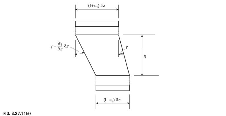
The compatibility of the displacement condition between longerons 1 and 2 is shown in Fig. S.27.11(e).
Thus,
from which
{\frac{\mathrm{d}\gamma}{\mathrm{d}z}}={\frac{1}{h}}(\varepsilon_{1}-\varepsilon_{2}) (iv)
In Eq. (iv), \gamma=q/G t,\,\varepsilon_{1}\!=\!P_{1}/3\,\,B E,\,\,\mathrm{and}\,\,\varepsilon_{2}\!=\!P_{2}/B E. Equation (iv) then becomes
{\frac{\mathrm{d}q}{\mathrm{d}z}}={\frac{G t}{h B E}}\left({\frac{P_{1}}{3}}-P_{2}\right) (v)
From Eq. (i),
{\frac{\mathrm{d}q}{\mathrm{d}z}}={\frac{\partial^{2}P_{1}}{\partial z^{2}}}and from Eq. (iii),
P_{2}=-P_{1}-{\frac{S z}{2h}}Substituting in Eq. (v),
{\frac{\partial^{2}P_{1}}{\partial z^{2}}}={\frac{G t}{h B E}}\left({\frac{4P_{1}}{3}}+{\frac{S z}{2h}}\right)or
{\frac{\partial^{2}P_{1}}{\partial z^{2}}}-{\frac{4G t}{3h B E}}P_{1}={\frac{G t S z}{2h^{2}B E}} (vi)
The solution of Eq. (vi) is
P_{1}=C\cosh\mu z+D\sinh\mu z-{\frac{3S z}{8h}} (vii)
where \mu^{2}{=}4G T/3h B E.
When z=0,P_{1}=0 so that, from Eq. (vii), C=0. When z=l, q=0 so that, from Eq. (i), \partial P_{1}/\partial z= –S/2h. Hence, from Eq. (vii),
D=-{\frac{S}{8h\mu\cosh\mu}}and Eq. (vii) becomes
P_{1}=-{\frac{S}{8h}}{\bigg(}{\frac{\sinh\mu z}{\mu\cosh\mu l}}+3z{\bigg)} (viii)
Substituting for {\mathbf{}}P_{1} in Eq. (i) gives
q=-{\frac{S}{8h}}\biggl({\frac{\cosh\mu z}{\cosh\mu l}}-1\biggr) (ix)
If the effect of shear lag is neglected, then Eq. (ix) reduces to
q={\frac{S}{8h}}and the shear flow distribution is that shown in Fig. S.27.11(f) in which q_{12}=q_{43}=q_{65}=q_{78}=5/8h and q_{81}=q_{54}=S/2h. The deflection Δ due to bending and shear is given by Eqs (20.17) and (20.19) in
which
\Delta_M=\frac{1}{E} \int_L\left(\frac{M_{y, 1}M_{y, 0}}{I_{y y}}+\frac{M_{x, 1} M_{x, 0}}{I_{xx}}\right) d z (20.17)
\Delta_S=\int_L\left(\int_{\text {sect }} \frac{q_0 q_1}{G t} d s\right) d z (20.19)
M_{0}=-S z\ \ \mathrm{and}\ \ M_{1}=-1\times zAlso, I_{\mathrm{xx}}=4\times3B\times(h/2)^{2}+4\times B\times(h/2)^{2}=4B h^{2}{\mathrm{~and~}}q_{1}=q_{0}/S. Thus,
\Delta=\int_0^L \frac{S z^2}{4 B h^2 E} dz+\int_0^l\left(\oint \frac{q_0 q_1}{G t} d s\right) d z (x)
In Eq. (x),
\oint \frac{q_0 q_1}{G t} d s=\frac{S}{G}\left(\frac{4 h}{64 h^2 t}+\frac{2 h}{4 h^2 3t}\right)=\frac{11 S}{48 G h t}Hence, substituting in Eq. (x),
\Delta={\frac{S I}{12h}}{\left({\frac{l^{2}}{B h E}}+{\frac{11}{4G t}}\right)}