Question 8.1: Calculate the fault current contributions of the following s......
Calculate the fault current contributions of the following synchronous machines, directly connected to a bus, using ANSI and IEC methods. Calculate the first-cycle (IEC peak) and interrupting (IEC breaking, symmetrical, and asymmetrical) currents for contact parting times of two cycles and three cycles (IEC minimum time delay = 0.03 and 0.05 s, approximately for a 60 Hz system). Compare the results.
● 110 MVA, 13.8 kV, 0.85 power factor generator, X^{\prime \prime}_{dv} = 16% on generator MVA base
● 50 MVA, 13.8 kV, 0.85 power factor generator, X^{\prime \prime}_{dv} = 11% on generator MVA base
● 2000 hp, 10-pole, 2.3 kV, 0.8 power factor synchronous motor, X^{\prime \prime}_{lr} = 20%
● 10,000 hp, 4-pole, 4 kV synchronous motor, 0.8 power factor, X^{\prime \prime}_{lr} = 15%
Learn more on how do we answer questions.
Table 8.4 shows the results of ANSI calculations. The first-cycle peak is calculated using Equation 7.1
I_{peak} = I_{ac \ peak} + I_{dc} = \sqrt{2} I_{ac,rms} (1 + e^{-2 \pi τ/(X/R)} ) = I_{ac \ peak}(1 + e^{-2 \pi τ/(X/R)} ) (7.1)
for new ratings of the breakers. These calculations have already been discussed in Chapter 7, and the description is not repeated here. Table 8.5 shows all the steps in IEC calculations. We will go through these steps for a sample calculation for a 110 MVA generator.
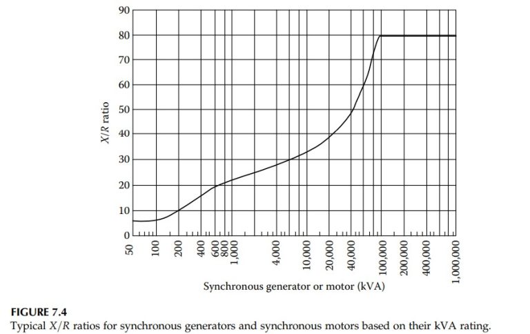
The percentage subtransient reactances for all the machines are the same in both calculations. The X/R ratio for ANSI calculations is estimated from Figure 7.4, while for IEC calculations, it is based on Equation 8.16.
R_{Gf} = 0.05 X^{\prime \prime}_{d} for generators with U_{rG}>1 \ kV and S_{rG}≥100 \ MVA
R_{Gf} = 0.07 X^{\prime \prime}_{d} for generators with U_{rG}>1 \ kV and S_{rG}<100 \ MVA
R_{Gf} = 0.15 X^{\prime \prime}_{d} for generators with U_{rG}≤1 \ kV (8.16)
For a 110 MVA generator, R_{Gf} = 0.05 X^{\prime \prime}_{d}, i.e., X/R = 20.
Next, factor K_{G} is calculated from Equation 8.14. This is based on a rated power factor of 0.85 of the generator:
K_{G}= \frac{U_{n}}{U_{rG}}(\frac{c_{max}}{1 \ + \ X^{\prime \prime}_{d} \sin \phi _{rG}})= \frac{1.10}{1 \ + \ 0.16 \ × \ 0.526}=1.05
In the above calculation, X^{\prime \prime}_{d} is in per unit on a machine MVA base at machine rated voltage and U_{n} = U_{rG}. From Equation 8.13, the modified generator impedance is
Z_{GK} = K_{G} (R_{G} + jX^{\prime \prime}_{d}) = 1.05(0.0073 + j0.1455) per unit 100 MVA base
The initial short-circuit current from Equation 8.2 is
I^{\prime \prime}_{k} = \frac{cU_{n}}{\sqrt{3}\sqrt{R_{k}^{2} + X^{2}_{k}}}= \frac{cU_{n}}{\sqrt{3}Z_{k}} (8.2)
|I^{\prime \prime}_{k}| = \frac{c_{max}}{|Z_{GK}|}= \frac{1.1}{0.153}=7.191 per unit = 30.09 kA
Here, we are interested in magnitude only, as the calculations are from a single source and summations are not involved. For the calculation of peak current, the factor x is calculated from Equation 8.4:
x = 1.02 +0.98e^{-3R/X} = 1.02 + 0.98 × 0.861 = 1.863
The peak current from Equation 8.3 is therefore
i_{p} = x \sqrt{2}I^{\prime \prime}_{k} = 1.863 ×\sqrt{2} ×30.09 = 79.27 \ kA
The breaking current factor μ is calculated from Equation 8.22.
μ = 0.84 + 0.26e^{-0.26I^{\prime \prime}_{kG}/I_{rG}} for t_{min}=0.02 \ s
μ = 0.71 + 0.51e^{-0.30I^{\prime \prime}_{kG}/I_{rG}} for t_{min}=0.05 \ s (8.22)
μ = 0.62 + 0.72e^{-0.32I^{\prime \prime}_{kG}/I_{rG}} for t_{min}=0.10 \ s
μ = 0.56 + 0.94e^{-0.38I^{\prime \prime}_{kG}/I_{rG}} for t_{min}≥0.25 \ s
For 0.05 minimum time delay:
μ = 0.71 + 0.51e^{-0.30I^{\prime \prime}_{kG}/I_{rG}} = 0.71 + 0.51e^{-0.30×30.09/4.60} = 0.78
The calculation for 0.03 minimum time delay is not given directly by Equations 8.22,
and interpolation is required. Alternatively, the factor can be estimated from the graphs in the IEC standard.
The symmetrical interrupting current at 0.05 s minimum time delay is
i_{bsym} = μ I^{\prime \prime}_{k} = 0.78 × 30.09 = 23.47 \ kA
The dc component is calculated from Equation 8.39.
i_{dc} = \sqrt{2} I^{\prime \prime}_{k}ε^{-ωt/X/R} (8.39)
However, to calculate X/R ratio R_{G} as calculated above is not used, as per qualification stated in section. Using an X/R of 80, the same as for the ANSI/IEEE calculation, gives
i_{dc} = \sqrt{2} I^{\prime \prime}_{k}e^{-ωt/X/R} = \sqrt{2} × 30.9 × e^{-377×0.05/80} = 34.52 \ kA
The asymmetrical breaking current at 0.05 s parting time is
i_{basym}= \sqrt{i_{bsym}^{2} + i_{dc}^2}=41.74 \ kA \ rms
Table 8.5 is compiled similarly for other machines. Synchronous motors are treated as synchronous generators for the calculations. A comparison of the results by two methods of calculation shows some differences. ANSI first-cycle current and IEC peak currents are comparable, with a difference within 3%. ANSI interrupting duty symmetrical currents for generators are higher than IEC breaking currents, i.e., for a 110 MVA generator, the ANSI current at 2-cycle contact parting time is 28.76 kA (without multiplying factor), while IEC current is 25.57 kA.
For comparison with IEC asymmetrical breaking current for 5-cycle breaker, from Table 8.5, i_{basym} = 41.74 kA, and, from Table 8.4, ANSI calculation, the interrupting sym rating is calculated as 34.62 kA. As per the rating structure of the breakers, the asymmetrical interrupting current is 1.1 × 34.62 = 38.08 kA. Thus, IEC calculation gives higher asymmetrical breaking current. Similarly, for 3-cycle breaker, i_{basym} = 45.74 kA, and as per ANSI calculation the corresponding number to compare is 1.2 × 34.20 = 41.04. In ANSI calculations, the short-circuit currents from the motors for various contact parting times do not change, and no remote or local multiplying factors are applicable to these currents.
| TABLE 8.4 ANSI Fault Current Calculations from Synchronous Generators and Motors Directly Connected to a Bus |
||||||||
| Description | Percentage X^{\prime \prime}_{d} on Equipment MVA Base | X/R | Impedance Multiplying Factors | First-Cycle Calculations | Interrupting Duty Calculations | |||
| First Cycle | Interrupting | First-Cycle Current (kA sym.) | First-Cycle Current (kA peak) | 3-Cycle Contact Parting Time (kA rms) | 2-Cycle Contact Parting Time (kA rms | |||
| 110 MVA, 0.85 pF, 13.8 kV generator |
16 | 80.0 | 1 | 1 | 28.76 | 79.81 | 34.62 MF = 1.204 |
34.20 MF = 1.189 |
| 50 MVA, 0.85 pF, 13.8 kV generator |
11 | 65.0 | 1 | 1 | 19.02 | 52.55 | 22.30 MF = 1.173 |
22.35 MF = 1.175 |
| 2000 hp, 10-pole, 2.3 kV synchronous motor, 0.8 pF (2000 kVA) |
20 | 25.0 | 1 | 1.5 | 2.51 | 6.67 | 1.67 | 1.67 |
| 10,000 hp, 4-pole, 4 kV synchronous motor, 0.8 pF (10,000 kVA |
15 | 34.4 | 1 | 1.5 | 9.62 | 25.99 | 6.41 | 6.41 |
| TABLE 8.5 IEC Fault Current Calculations from Synchronous Generators and Motors Directly Connected to a Bus, Three-Phase Short-Circuit |
||||
| Equipment | 110 MVA, 0.85 pF, 13.8 kV Generator | 50 MVA, 0.85 pF, 13.8 kV Generator | 2000 hp, 10-pole, 0.8 pF, 2.4 kV Synchronous Motor | 10,000 hp, 4-pole, 0.8 pF, 4 kV Synchronous Motor |
| PercentageX^{\prime \prime}_{d} on equipment kVA base | 16 | 11 | 20 | 15 |
| R_{G} or R_{M} | 0.05 X^{\prime \prime}_{d} | 0.07 X^{\prime \prime}_{d} | 0.07 X^{\prime \prime}_{d} | 0.07 X^{\prime \prime}_{d} |
| X/R for dc component | 80 | 65 | — | — |
| c_{max} | 1.1 | 1.1 | 1.1 | 1.1 |
| K_{G} or K_{M} | 1.015 | 1.04 | 0.982 | 1.01 |
| I^{\prime \prime}_{kG} or I^{\prime \prime}_{kM} kA rms | 30.09 | 20.06 | 2.68 | 10.45 |
| κ | 1.863 | 1.814 | 1.814 | 1.814 |
| i_{p} kA peak | 79.27 | 51.46 | 6.88 | 26.80 |
| μ (0.05 s) | 0.78 | 0.74 | 0.81 | 0.73 |
| μ (0.03 s) | 0.85 | 0.82 | 0.85 | 0.81 |
| i_{bsym} (0.05 s) | 23.47 | 14.84 | 2.17 | 7.63 |
| i_{bsym} (0.03 s) | 25.57 | 16.45 | 2.28 | 8.46 |
| I_{DC} (0.05 s) kA | 34.52 | 21.22 | 1.01 | 3.95 |
| I_{DC} (0.03 s) kA | 37.93 | 23.80 | 1.72 | 6.70 |
| i_{basym} (0.05 s) kA | 41.74 | 25.89 | 2.39 | 8.50 |
| i_{basym} (0.03 s) kA | 45.74 | 28.90 | 2.86 | 10.79 |