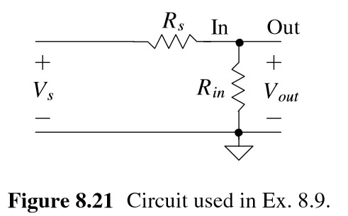
Question 8.9: Calculate the input-referred noise, F, and SNRs for the circ......
Calculate the input-referred noise, F, and SNRs for the circuit seen in Fig. 8.21.

Learn more on how do we answer questions.
Let’s begin by adding the noise voltage spectral density to the circuit, Fig. 8.22a. The output noise PSD is
V_{o n o i s e}^{2}(f)=4k T R_{s}\biggl[\frac{R_{i n}}{R_{i n}+R_{s}}\biggr]^{2}+4k T R_{i n}\biggl[\frac{R_{s}}{R_{i n}+R_{s}}\biggr]^{2}To determine V_{o n o i s e,R M S}, we integrate this PSD over the bandwidth of interest B or
V_{o n o i s e,R M S}^{2}=\int_{f_{L}}^{f_{H}}V_{o n o i s e}^{2}(f)\cdot d f=4k T B R_{s}\biggl[{\frac{R_{i n}}{R_{i n}+R_{s}}}\biggr]^{2}+4k T B R_{i n}\biggl[{\frac{R_{s}}{R_{i n}+R_{s}}}\biggr]^{2}
Noting our gain A (= V_{_{o u t}}/V_{i n} not V_{_{o u t}}/V_{s}) is one, we can use the model shown in Fig. 8.22b. To determine the input-referred noise sources, we can use Eq. (8.32) and the results in Ex. 8.7. To determine \textstyle V_{i n o i s e,R M S}, we short the input to ground (R_{s}=0 in Fig. 8.21 and the equation above), Fig. 8.22c, and equate the circuit output to \textstyle V_{o n o i s e,R M S}. This gives
V_{o n o i s e,R M S}^{2}=4k T R_{s}B\cdot\left(\frac{A R_{i n}}{R_{s}+R_{i n}}\right)^{2}+I_{i n o i s e,R M S}^{2}\cdot\left(\frac{A R_{s}R_{i n}}{R_{s}+R_{i n}}\right)^{2}+V_{i n o i s e,R M S}^{2}\cdot\left(\frac{A R_{i n}}{R_{s}+R_{i n}}\right)^{2} (8.32)
V_{o n o i s e,R M S,Rs=0}=V_{i n o i s e,R M S}=0
To determine \textstyle I_{i n o i s e,R M S}, we open the input (R_{s}=∞ ), Fig. 8.22d, and equate the Rs circuit’s output to \textstyle V_{o n o i s e,R M S} (from the equation above). This gives
R_{i n}^{2}\cdot I_{i n o i s e,R M S}^{2}=V_{o n o i s e,R M S,R s=\infin }^{2}=4k T B R_{i n}\to I_{i n o i s e,R M S}=\sqrt{\frac{4k T B}{R_{i n}}}
The input SNR is given in Eq. (8.29). The output SNR, Fig. 8.22e, is
S N R_{i n}=\frac{V_{s,R M S}^{2}\cdot\left[\frac{R_{i n}}{R_{i n}+R_{s}}\right]^{2}}{4k T R_{s}B\cdot\left[\frac{R_{i n}}{R_{i n}+R_{s}}\right]^{2}}=\frac{V_{s,R M S}^{2}}{4k T R_{s}B} (8.29)
\mathrm{SN}R_{o u t}={\frac{V_{s,R M S}^{2}\cdot\left[{\frac{R_{i n}}{R_{s^{+}R_{i n}}}}\right]^{2}}{V_{o n o i s e,R M S}^{2}}}={\frac{V_{s,R M S}^{2}}{4k T B\cdot R_{s}(1+R_{s}/R_{i n})}} (8.40)
The noise factor is then
F=1+\frac{R_{s}}{R_{i n}} (8.41)
To minimize the NF, we can decrease R_{s} or increase R_{in}. Decreasing R_{s} causes SNR_{in} and SNR_{out} to increase, as seen in Eqs. (8.29) and (8.40). At the same time, increasing R_{in} causes SNR_{out} to move towards SNR_{in}, Eq. (8.40), resulting in F moving towards 1.
