Question 24.2: Calculate the shear flows in the web panels and direct load ......
Calculate the shear flows in the web panels and direct load in the flanges and stiffeners of the beam shown in Fig. P.24.2 if the web panels resist shear stresses only.

Learn more on how do we answer questions.
Referring to Fig. P.24.2 and considering the vertical equilibrium of the stiffener CDF,
8000\sin30^{\circ}-q_{1}\times200-q_{2}\times200=0from which
q_{1}+q_{2}=20 (i)
Now, considering the horizontal equilibrium of the stiffener ED,
8000\mathrm{cos}\,30^{\circ}-q_{1}\times300+q_{2}\times300=0whence,
q_{1}-q_{2}=23.1 (ii)
Adding Eqs (i) and (ii),
2q_{1}=43.1i.e.,
q_{1}=21.6\mathrm{N/mm}so that, from Eq. (i),
q_{2}=-1.6\mathrm{N/mm}The vertical shear load at any section in the panel ABEGH is 8000 sin 30° =4000N. Hence,
400q_{3}=4000i.e.,
q_{3}=10\mathrm{N/mm}Now consider the equilibrium of the flange ABC in Fig. S.24.2(a). At any section z between C and B,
P_{\mathrm{CB}}=21.6z (iii)
so that P_{\mathrm{{CB}}} varies linearly from zero at C to 6480 N (tension) at B. Also at any section z between B and A,
P_{\mathrm{BA}}=21.6\times300+10(z-300)i.e.,
P_{\mathrm{BA}}=3480+10z (iv)
Thus P_{\mathrm{BA}} varies linearly from 6480 N (tension) at B to 9480 N (tension) at A.
Referring to Fig. S.24.2(b) for the bottom flange HGF, the flange load P_{\mathrm{{FG}}} at any section z is given by
P_{\mathrm{FG}}=1.6z (v)
Thus P_{\mathrm{{FG}}} varies linearly from zero at F to 480 N (tension) at G. Also at any section z between G and H,
P_{\mathrm{GH}}+10(z-300)-1.6\times300=0i.e.,
P_{\mathrm{GH}}=3480-10z (vi)
Hence, P_{\mathrm{GH}} varies linearly from 480 N (tension) at G to –2520 N (compression) at H.
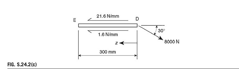
The forces acting on the stiffener DE are shown in Fig. S.24.2(c). At any section a distance z from D,
i.e.,
P_{\mathrm{DE}}=-23.2z+6928.2 (vii)
Therefore, P_{\mathrm{{DE}}} varies linearly from 6928 N (tension) at D to zero at E. (The small value of P_{\mathrm{{DE}}} at E
given by Eq. (vii) is due to rounding-off errors in the values of the shear flows.)
The forces in the stiffener CDF are shown in Fig. S.24.2(d). At any section in CD a distance h from C the stiffener load, P_{\mathrm{CD}}, is given by
P_{\mathrm{CD}}=21.6h (viii)
so that P_{\mathrm{CD}}, varies linearly from zero at C to 4320 N (tension) at D. In DF,
P_{\mathrm{DF}}+8000\sin30^{\circ}+1.6(h-200)-21.6\times200=0from which
P_{\mathrm{DF}}=640-1.6h (ix)
Hence, P_{\mathrm{DF}} varies linearly from 320 N (tension) at D to zero at F.
The stiffener BEG is shown in Fig. S.24.2(e). In BE, at any section a distance h from B,
i.e.,
P_{\mathrm{BE}}=-11.6h (x)
P_{\mathrm{BE}} therefore varies linearly from zero at B to –2320 N (compression) at E. In EG,
P_{\mathrm{EG}}-1.6(h-200)+21.6\times200-10h=0i.e.,
P_{\mathrm{{EG}}}=11.6h-4640 (xi)
Thus P_{\mathrm{EG}} varies linearly from –2320N (compression) at E to zero at G.