Question 5.10: Design a BCD-to-decimal decoder with the use of a decoder....
Design a BCD-to-decimal decoder with the use of a decoder.
Learn more on how do we answer questions.
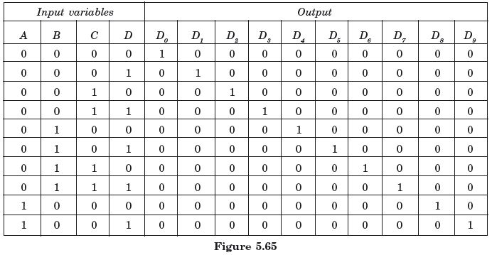
BCD code uses four bits to represent its different numbers from 0 to 9. So he decoder should have four input lines and ten output lines. By simple method a BCD to- decimal coder may use a 4-to-16 line decoder. But at output, six lines are illegal and they are deactivated with the use of AND gates or any other means. However, a 3-to-8 line decoder may be employed for this purpose with its intelligent utilization. A partial truth table of a BCD-to-decimal decoder is shown in Figure 5.65.
Since the circuit has ten outputs, ten Karnaugh maps are drawn to simplify each one of the outputs. However, it would be useful to construct a single map similar to a Karnaugh map indicating the outputs and don’t-care conditions as in Figure 5.66. It can be seen that pairs and groups may be formed considering the don’t-care conditions.
The Boolean expressions of the different outputs may be written as
Figure 5.67 illustrates the complete circuit diagram of a BCD decoder implemented with a 3-to-8 decoder IC, with B, C, and D as input lines to the decoder.