Question 2.3: Figure 2.15a shows a 5 MVA 34.5–2.4 kV delta–delta transform......
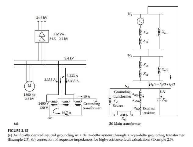
Figure 2.15a shows a 5 MVA 34.5–2.4 kV delta–delta transformer serving industrial motor loads. It is required to derive an artificial neutral through a wye–delta-connected transformer and highresistance ground the 2.4 kV secondary system through a grounding resistor. The capacitance charging current of the system is 8 A. Calculate the value of the resistor to limit the ground fault current through the resistor to 10 A. Neglect transformer resistance and source resistance.
Learn more on how do we answer questions.
The connection of sequence networks is shown in Figure 2.15b and the given impedance data reduced to a common 100 MVA base are shown in Table 2.3. Motor wye-connected neutrals are left ungrounded in the industrial systems, and therefore motor zero sequence impedance is infinite. (This contrasts with grounding practices in some European countries, where the motor neutrals are grounded.) The source zero sequence impedance can be calculated based on the assumption of equal positive and negative sequence reactances. The motor voltage is 2.3 kV, and, therefore, its per unit reactance on 100 MVA base is given by
(\frac{16.7}{1.64}) (\frac{ 2.3}{2.4})^2 = 9.35
Similarly, the grounding transformer per unit calculations should be adjusted for correct voltages:
X_{0} = (\frac{1.5}{0.06})(\frac{2.4}{2.4/ \sqrt{3}})^2 = 75
The equivalent positive and negative sequence reactances are as follows: 1.41 per unit each. The zero sequence impedance of the grounding transformer is 50 + j75 per unit. The total fault current should be limited to 10 – j8 = 12.80 A. Thus, the required impedance is
Z_{t} = (\frac{2400/ \sqrt{3}}{12.8/3})= 324.8 \ ohm
The base ohms (100 MVA base) = 0.0576. The required Z_{t} = 324.8/base ohms = 5638.9 per unit. This shows that the system positive and negative sequence impedances are low compared to the desired total impedance in the neutral circuit. The system positive and negative sequence impedances can, therefore, be neglected.
I_{R0} = 10/3 = 3.33 A. Therefore, Z_{R0}= (2400/ \sqrt{3} )/3.33 = 416.09 ohm = 416.09=base ohms = 7223.9 per unit. The additional resistor to be inserted is given by the expression:
R_{R0} = \sqrt{Z_{R0} – X_{tG0}} – R_{tG0}\\= \sqrt{7223.9^2 – 75^2} – 50\\= 7173.5~pu
where
R_{R0} is the added resistor
Z_{R0} is the total impedance in the ground circuit
X_{tG0} and R_{tG0} are reactance and resistance of the grounding transformer as in Figure 2.15b
Multiplying by base ohms, the required resistance = 413.2 ohm
These values are in symmetrical component equivalents. In actual values, referred to 120 V secondary, the resistance value is
R_{R} = (\frac{120}{2400})^2 413.2 × 3 = 3.1 \ ohm
If we had ignored all the sequence impedances, including that of the grounding transformer, the calculated value is 3.12 ohm. This is often done in the calculations for grounding resistance for high-resistance grounded systems, and all impedances including that of the grounding transformer can be ignored without appreciable error in the final results. The grounding transformer should be rated to permit continuous operation, with a ground fault on the system. The per phase grounding transformer kVA requirement is 2.4 (kV) × 3.33 A = 8 kVA, that is, a total of 8 × 3 = 24 kVA. The grounding transformer of the example is, therefore, adequately rated.
| TABLE 2.3 Impedance Data for Example 2.3—High-Resistance Grounding |
||||
| Equipment | Given Data | Per Unit Impedance on 100 MVA Base | ||
| 34.5 kV source | Three-phase fault = 1500 MVA Line-to-ground fault = 20 kA sym |
X_{s1}=X_{s2} = 0.067 | ||
| 34.5–2.4 kV, 5 MVA transformer, delta–delta-connected |
X_{1}=X_{2}=X_{0} = 8% | X_{s0} = 0.116 | ||
| 2.3 kV 1800 hp (1640 kVA) induction motor load | Locked rotor reactance = 16.7% (on motor base kVA) | X_{m1}=X_{m2} = 9.35 | ||
| Grounding transformer, 60 kVA, wye–delta-connected 2400:120 V |
X_{0} = 1.5% | X_{0} = 75 | ||
| R_{0} = 1.0% | R_{0} = 50 | |||