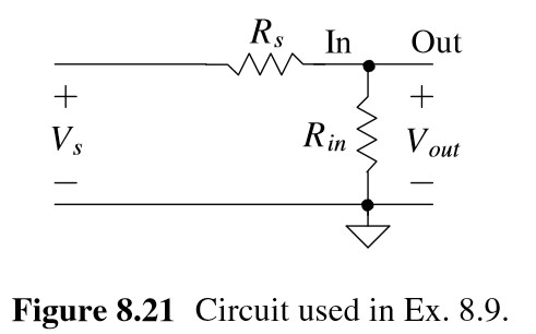
Question 8.10: Suppose, in Fig. 8.21, Rs is 10k and Rin is 1k. Use SPICE to......
Suppose, in Fig. 8.21, R_{s} is 10k and R_{in} is 1k. Use SPICE to verify the value of noise factor derived in Ex. 8.9 (that is, Eq. [8.41]).
{F}=1+\frac{R_{s}}{R_{i n}} (8.41)
Learn more on how do we answer questions.
Using Eq. (8.41), the noise factor is 11 (NF = 10.4 dB). Note that Eq. (8.41) is not dependent on bandwidth. We simulated this circuit already in Ex. 8.5 over a bandwidth of 1 to 1kHz. The result was a V_{o n o i s e,R M S}^{2} of 1.5053\times10^{-14}\ { V}^{2}\,. Referring to Eq. (8.37), this is the “total output noise power.” To determine the “output noise power due to source resistance,” we can replace R_{in} with a noiseless resistor, as seen in Fig. 8.24. The SPICE netlist is given below.
{F}=\frac{\mathrm{total~output~noise~power}}{\mathrm{output~noise~power~to~source~resistance}} (8.37)
The noise factor is calculated from the simulation results as
F=\frac{1.50353\times10^{-14}\ V^{2}}{1.3685\times10^{-15}\ V^{2}}=11which is what we calculated using Eq. (8.41).
*** Example 8.10 CMOS: Circuit Design, Layout, and Simulation ***
.control
destroy all
run
print all
.endc
.noise V(Vout,0) Vs dec 100 1 1k
Rs Vs Vout 10k
Gin Vout 0 Vout 0 1e-3
Vs Vs 0 dc 0 ac 1
.print noise all
.end
TEMP=27 deg C
Noise analysis … 100%
inoise_total = 1.655918e-13
onoise_total = 1.368527e-15
