Question 7.17: Use PSpice to find the response i(t) for t > 0 in the c......
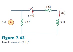
Use PSpice to find the response i(t) for t > 0 in the circuit of Fig. 7.63
Learn more on how do we answer questions.
Solving this problem by hand gives i(0) = 0 , i(∞) = 2 A , R_{Th} = 6 , \tau = 3/6 = 0.5 s , so that
i(t) = i(∞) + [i(0) – i(∞) ] e^{-t/\tau} = 2(1 – e^{-2t} ) , t > 0
To use PSpice, we first draw the schematic as shown in Fig. 7.64. We recall from Appendix D that the part name for a closed switch is Sw_tclose. We do not need to specify the initial condition of the inductor because PSpice will determine that from the circuit. By selecting Analysis/Setup/Transient, we set Print Step to 25 ms and Final Step to 5\tau = 2.5 s . After saving the circuit, we simulate by selecting Analysis/Simulate. In the PSpice A/D window, we select Trace/Add and display –I(L1) as the current through the inductor. Figure 7.65 shows the plot of i(t) which agrees with that obtained by hand calculation.
Note that the negative sign on I(L1) is needed because the current enters through the upper terminal of the inductor, which happens to be the negative terminal after one counterclockwise rotation. A way to avoid the negative sign is to ensure that current enters pin 1 of the inductor. To obtain this desired direction of positive current flow, the initially horizontal inductor symbol should be rotated counterclockwise 270° and placed in the desired location.

