Question 7.1: A compressed-air tank having an inner diameter of 450 mm and...
A compressed-air tank having an inner diameter of 450 mm and a wall thickness of 7 mm is formed by welding two steel hemispheres (Fig. 7-5).
(a) If the allowable tensile stress in the steel is 115 MPa, what is the maximum permissible air pressure p_a in the tank?
(b) If the allowable shear stress in the steel is 40 MPa, what is the maximum permissible pressure p_b?
(c) If the normal strain at the outer surface of the tank is not to exceed 0.0003, what is the maximum permissible pressure p_c? (Assume that Hooke’s law is valid and that the modulus of elasticity for the steel is 210 GPa and Poisson’s ratio is 0.28.)
(d) Tests on the welded seam show that failure occurs when the tensile load on the welds exceeds 1.5 MN/m per mm of weld. If the required factor of safety against failure of the weld is 2.5, what is the maximum permissible pressure p_d?
(e) Considering the four preceding factors, what is the allowable pressure p_{allow} in the tank?

Learn more on how we answer questions.
(a) Allowable pressure based upon the tensile stress in the steel. The maximum tensile stress in the wall of the tank is given by the formula σ = pr/2t (see Eq. 7-1). Solving this equation for the pressure in terms of the allowable stress, we get
frac{pr}{2t} (7-1)
p_a=\frac{2t\sigma _{allow}}{r} = \frac{2(7 mm)(115 MPa)}{225 mm} = 7.16 MPa
Thus, the maximum allowable pressure based upon tension in the wall of the tank is p_a = 7.1 MPa. (Note that in a calculation of this kind, we round downward, not upward.)
(b) Allowable pressure based upon the shear stress in the steel. The maximum shear stress in the wall of the tank is given by Eq. (7-3), from which we get the following equation for the pressure:
\tau _{max}=\frac{\sigma }{2}=\frac{pr}{4t} (7-3)
p_b=\frac{4t\tau _{allow}}{r} = \frac{4(7 mm)(40 MPa)}{225 mm} = 4.98 MPa
Therefore, the allowable pressure based upon shear is p_b = 4.9 MPa.
(c) Allowable pressure based upon the normal strain in the steel. The normal strain is obtained from Hooke’s law for biaxial stress (Eq. 6 39a):
\epsilon _x=\frac{1}{E} (\sigma _x-\nu \sigma _y) (6 39a) (h)
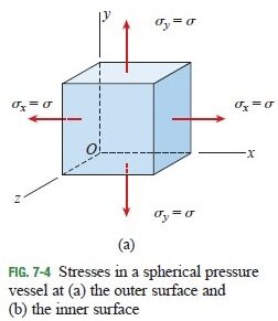
Substituting \sigma _x = \sigma _y =\sigma =pr/2t (see Fig. 7-4a), we obtain
\epsilon _x=\frac{\sigma}{E} (1-\nu )=\frac{pr}{2tE} (1-\nu ) (7-4)
This equation can be solved for the pressure p_c:
p_c=\frac{2tE\epsilon _{allow}}{r(1-\nu )} =\frac{2(7 mm)(210 GPa)(0.0003)}{(225 mm)(1 – 0.28)} = 5.44 MPa
Thus, the allowable pressure based upon the normal strain in the wall is p_c = 5.4 MPa.
(d) Allowable pressure based upon the tension in the welded seam. The allowable tensile load on the welded seam is equal to the failure load divided by the factor of safety:
T_{allow}=\frac{T_{failure}}{n} =\frac{1.5 MN/m}{2.5} =0.6 MN/m = 600 N/mm
The corresponding allowable tensile stress is equal to the allowable load on a one millimeter length of weld divided by the cross-sectional area of a one millimeter length of weld:
\sigma _{allow}=\frac{T_{allow}(1 mm)}{(1 mm)(t)} =\frac{(600 N/mm)(1 mm)}{(1 mm)(7 mm)} = 85.7 MPa
Finally, we solve for the internal pressure by using Eq. (7-1):
p_d=\frac{2t\sigma _{allow}}{r} =\frac{2(7 mm)(85.7 MPa)}{225 mm} = 5.3 MPa
This result gives the allowable pressure based upon tension in the welded seam.
(e) Allowable pressure. Comparing the preceding results for p_a , p_b , p_c , and p_d , we see that shear stress in the wall governs and the allowable pressure in the tank is
p_{allow} = 4.9 MPa
This example illustrates how various stresses and strains enter into the design of a spherical pressure vessel.
Note: When the internal pressure is at its maximum allowable value (4.9 MPa), the tensile stresses in the shell are
\sigma =\frac{pr}{2t} =\frac{(4.9 MPa)(225 mm)}{2(7 mm)} = 78.8 MPa
Thus, at the inner surface of the shell (Fig. 7-4b), the ratio of the principal stress in the z direction (4.9 MPa) to the in-plane principal stresses (78.8 MPa) is only 0.062. Therefore, our earlier assumption that we can disregard the principal stress \sigma_3 in the z direction and consider the entire shell to be in biaxial stress is justified.