Question 9.18: A simple beam with an overhang supports a uniform load of an...
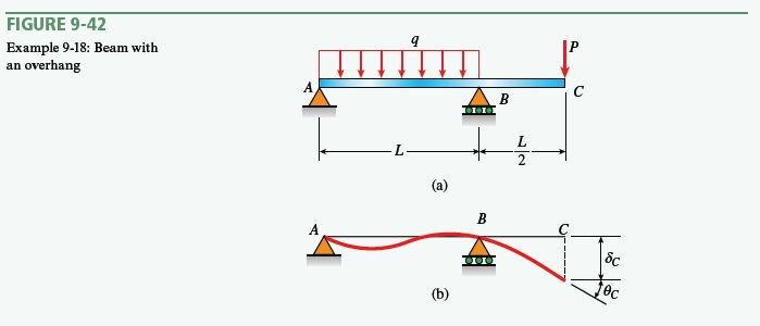
A simple beam with an overhang supports a uniform load of an intensity q on span AB and a concentrated load P at end C of the overhang (Fig. 9-42).
Determine (a) the deflection δ_{C} and (b) angle of rotation θ_{C} at point C. Use the modified form of Castigliano’s theorem.
Learn more on how we answer questions.
Use a four-step problem-solving approach. Combine steps as needed for an efficient solution.
Part (a): Deflection \delta_{C} at the end of overhang.
1, 2. Conceptualize, Categorize: Since the load P corresponds to this deflection (Fig. 9-42), a fictitious load is not needed. Instead, begin immediately to find the bending moments throughout the length of the beam. The reaction at support A is
as shown in Fig. 9-43. Therefore, the bending moment in span AB is
M_{A B}=R_{A} x_{1}-\frac{q x_{1}^{2}}{2}=\frac{q L x_{1}}{2}-\frac{P x_{1}}{2}-\frac{q x_{1}^{2}}{2} \quad\left(0 \leq x_{1} \leq L\right)where x_{1} is measured from support A (Fig. 9-43). The bending moment in the overhang is
M_{B C}=-P x_{2} \quad\left(0 \leq x_{2} \leq \frac{L}{2}\right)where x_{2} is measured from point C (Fig. 9-43).
Next, determine the partial derivatives with respect to the load P:
\frac{\partial M_{A B}}{\partial P}=-\frac{x_{1}}{2} \quad\left(0 \leq x_{1} \leq L\right)\frac{\partial M_{B C}}{\partial P}=-x_{2} \quad\left(0 \leq x_{2} \leq \frac{L}{2}\right)
3. Analyze: Now use the modified form of Castigliano’s theorem [Eq. (9-118)] to obtain the deflection at point C:
\delta_{i}=\frac{\partial}{\partial P_{i}} \int \frac{M^{2} d x}{2 E I}=\int\left(\frac{M}{E I}\right)\left(\frac{\partial M}{\partial P_{i}}\right) d x (9-118)
\delta_{C}=\int\left(\frac{M}{E I}\right)\left(\frac{\partial M}{\partial P}\right) d x= \frac{1}{E I} \int_{0}^{L} M_{A B}\left(\frac{\partial M_{A B}}{\partial P}\right) d x+\frac{1}{E I} \int_{0}^{L / 2} M_{B C}\left(\frac{\partial M_{B C}}{\partial P}\right) d x
Substitute the expressions for the bending moments and partial derivatives to get
\delta_{C}=\frac{1}{E I} \int_{0}^{L}\left(\frac{q L x_{1}}{2}-\frac{P x_{1}}{2}-\frac{q x_{1}^{2}}{2}\right)\left(-\frac{x_{1}}{2}\right) d x_{1}+\frac{1}{E I} \int_{0}^{L / 2}\left(-P x_{2}\right)\left(-x_{2}\right) d x_{2}Perform the integrations and combining terms to obtain the deflection:
\delta_{C}=\frac{P L^{3}}{8 E I}-\frac{q L^{4}}{48 E I} (9-120)
4. Finalize: Since the load P acts downward, the deflection \delta_{C} is also positive downward. In other words, if the preceding equation produces a positive result, the deflection is downward. If the result is negative, the deflection is upward.
Compare the two terms in Eq. (9-120) to see that the deflection at the end of the overhang is downward when P > qL / 6 and upward when P < qL / 6.
Part (a): Angle of rotation \theta_{C} at the end of overhang.
1, 2. Conceptualize, Categorize: Since there is no load on the original beam (Fig. 9-42a) corresponding to this angle of rotation (Fig. 9-42b), supply a fictitious load. Place a couple of moment M_{C} at point C (Fig. 9-44). Note that the couple M_{C} acts at the point on the beam where the angle of rotation is to be determined. Furthermore, it has the same clockwise direction as the angle of rotation (Fig. 9-42).
Follow the same steps as when determining the deflection at C. First, note that the reaction at support A (Fig. 9-44) is
Consequently, the bending moment in span AB becomes
M_{A B}=R_{A} x_{1}-\frac{q x_{1}^{2}}{2}=\frac{q L x_{1}}{2}-\frac{P x_{1}}{2}-\frac{M_{C} x_{1}}{L}-\frac{q x_{1}^{2}}{2} \quad\left(0 \leq x_{1} \leq L\right)Also, the bending moment in the overhang becomes
M_{B C}=-P x_{2}-M_{C} \quad\left(0 \leq x_{2} \leq \frac{L}{2}\right)The partial derivatives are taken with respect to the moment M_{C}, which is the load corresponding to the angle of rotation. Therefore,
\frac{\partial M_{A B}}{\partial M_{C}}=-\frac{x_{1}}{L} \quad\left(0 \leq x_{1} \leq L\right)\frac{\partial M_{B C}}{\partial M_{C}}=-1 \quad\left(0 \leq x_{2} \leq \frac{L}{2}\right)
3. Analyze: Now use the modified form of Castigliano’s theorem [Eq.(9-118)] to obtain the angle of rotation at point C:
\theta_{C}=\int\left(\frac{M}{E I}\right)\left(\frac{\partial M}{\partial M_{C}}\right) d x= \frac{1}{E I} \int_{0}^{L} M_{A B}\left(\frac{\partial M_{A B}}{\partial M_{C}}\right) d x+\frac{1}{E I} \int_{0}^{L / 2} M_{B C}\left(\frac{\partial M_{B C}}{\partial M_{C}}\right) d x
Substitute the expressions for the bending moments and partial derivatives to obtain
\theta_{C}=\frac{1}{E I} \int\left(\frac{q L x_{1}}{2}-\frac{P x_{1}}{2}-\frac{M_{C} x_{1}}{L}-\frac{q x_{1}^{2}}{2}\right)\left(-\frac{x_{1}}{L}\right) d x_{1}+ \frac{1}{E I} \int_{0}^{L / 2}\left(-P x_{2}-M_{C}\right)(-1) d x_{2}
Since M_{C} is a fictitious load, and since the partial derivatives have already been taken, set M_{C} equal to zero at this stage of the calculations and simplify the integrations:
\theta_{C}=\frac{1}{E I} \int_{0}^{L}\left(\frac{q L x_{1}}{2}-\frac{P x_{1}}{2}-\frac{q x_{1}^{2}}{2}\right)\left(-\frac{x_{1}}{L}\right) d x_{1}+\frac{1}{E I} \int_{0}^{L / 2}\left(-P x_{2}\right)(-1) d x_{2}After carrying out the integrations and combining terms, the rotation at C is
\theta_{C}=\frac{7 P L^{2}}{24 E I}-\frac{q L^{3}}{24 E I} (9-121)
4. Finalize: If this equation produces a positive result, the angle of rotation is clockwise. If the result is negative, the angle is counterclockwise.
Comparing the two terms in Eq. (9-121), note that the angle of rotation is clockwise when P > qL / 7 and counterclockwise when P < qL / 7.
If numerical data are available, it is now a routine matter to substitute numerical values into Eqs. (9-120) and (9-121) and calculate the deflection and angle of rotation at the end of the overhang.

