Question 5.20: A Single-Link Robot Arm The mechanical model of a single-lin...
A Single-Link Robot Arm
The mechanical model of a single-link robot arm driven by a motor can be represented as a gear–train system, as shown in Figure 5.97, in which two rotational subsystems are coupled with a pair of gears with negligible inertia. The mass moments of inertia of the motor and the load are I_m and I, respectively. The coefficients of torsional viscous damping of the motor and the load are B_m and B, respectively. τ_m is the torque generated by the motor. Assume that the gear ratio is N = r_1/r_2. Derive the differential equation of motion in terms of the motor variable θ_m.

Learn more on how we answer questions.
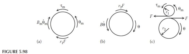
The free-body diagrams for the motor, the load, and the gear–train are shown in Figure 5.98, where F represents the contact force between the two gears. The moments caused by the contact force on the motor and on the load are r_1F and r_2F, respectively. Applying the moment equation to the motor and the load gives
+ \curvearrowleft : \sum M_O = I_O \alpha
τ_m – B_m\dot{θ}_m – r_1F = I_m\ddot{θ}_m
and
+ \curvearrowright : \sum M_O = I_O \alpha
– B_m\dot{θ} – r_2F = I_m\ddot{θ}
Solving for F from the equation for the load and substituting it into the equation for the motor results in
τ_m – B_m\dot{θ}_m – \frac{r_1}{r_2}(I\ddot{θ} + B\dot{θ}) I_m\ddot{θ}_m=
By the geometry of the gears,
\dot{θ} =\frac{r_1}{r_2}\dot{θ}_m = N\dot{θ}_m
\ddot{θ} =\frac{r_1}{r_2}\ddot{θ}_m = N\ddot{θ}_m
Substituting these into the previous differential equation gives
τ_m – B_m\dot{θ}_m – N^2 (I\ddot{θ}_m + B\dot{θ}_m) = I_m\ddot{θ}_m
which can be rearranged as
(I_m N^2I)\ddot{θ}_m + (B_m + N^2B)\dot{θ}_m = τ_m
The equation is in terms of the angular displacement of the motor.