Goal Find a relationship between the output and input moments when the gear train is in equilibrium. based on Figure 1, the requested ratio is M_{out} /M_{in} = r_{2} F_{out}/ r_{1}F_{in} . In addition, find the loads at the journal bearings at A, B, C, and D in terms of F_{in}.
Given The geometry of the gear train and that the bearings are frictionless.
The input is via Gear 1, and the output is via Gear 2.
Assume The weight of various members that make up the gear train can be ignored and the journal bearings are frictionless (we will check this assumption in Example 9.2.4). because there must be a boundary connection to prevent the shafts from sliding in the x direction, and we are not told whether any of the bearings acts as a thrust bearing (Table 4.2), we arbitrarily assume that bearings B and D act as thrust bearings (and will check this assumption in our analysis).
²Gear trains are used in rotating systems to either increase or decrease moment or to decrease or increase rotational speed. In an automotive transmission, which is an example of a gear train, the moment from the engine (the input into the transmission) is increased and the rotational speed is decreased relative to the drive shaft (the output from the transmission). Often the input and output moments acting around a shaft are referred to as “torques.”
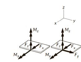
Draw We draw free-body diagrams for Shaft 1 and Shaft 2 in Figure 2. Notice that a third-law force pair acts between Gears 1 and 2.
Formulate Equations and Solve From the free -body diagram of Shaft 1 we can write:
M_{in} = (r_{1})(F_{in})
\sum{M_{ x} }\left(\curvearrowleft + \right) =M_{in} – (r_{1})(F_{12}) =0
F_{12} =\frac{M_{in}}{r_{1}}
Similarly, from the free-body diagram of Shaft 2 we can write:
M_{out} = (r_{2})(F_{out})
\sum{M_{x} }\left(\curvearrowleft + \right) =M_{out} – (r_{2})(F_{21}) =0
F_{21} =\frac{M_{out}}{r_{2}}
From Newton’s third law, we know that F_{12} = F_{21} . Therefore, we can write:
M_{out} = r_{2}\frac{M_{in}}{r_{1}}
Substituting in for r_{1} = 25 mm and r_{2} = 35 mm, we find that the requested ratio of M_{out}/M_{in} is 1.4.
The mechanical advantage of the gear train is 1.4
Now we go about finding the forces acting at the bearings at A, B, C, and D, as requested in part (b) of this example.
We find the forces at A and B based on the free-body diagram for Shaft 1 by writing:
\sum{F_{x} \left(\rightarrow + \right) } = 0\Rightarrow F_{Ax}=0 (1)
\sum{M_{z @ B} }\left(\curvearrowleft + \right) =F_{in}r_{1}- F_{12}r_{1}=0 (2)
Therefore, F_{in} = F_{12} (and we will use this finding in writing the next batch of equilibrium equations).
\sum{F_{y}\left(\uparrow + \right) } =- 2F_{in}+ F_{Ay}+F_{By} =0 (3)
\sum{F_{z}}=F_{Az}+F_{Bz} =0 (4)
\sum{M_{z @ B} }\left(\curvearrowleft + \right) = -2F_{in}a+ F_{Ay}\left(a+ a\right) =0
From this set of equations, we find that:
F_{Ay}=F_{By}=F_{in} and F_{Ax}=F_{Az}=F_{Bz}=0
We find the forces at C and D based on the free-body diagram for Shaft 2 by writing:
\sum{M_{x @ D} }\left(\curvearrowleft + \right) =F_{out}r_{1}- F_{21}r_{1}=0 (5)
Therefore, F_{out}= F_{21} . We also know from part (a), that F_{21}= F_{12} , therefore, F_{out}= F_{in} .
\sum{F_{x} \left(\rightarrow + \right) } = 0\Rightarrow F_{Cx}=0 (1)
\sum{F_{y}\left(\uparrow + \right) } =2F_{in}+F_{Cy} + F_{Dy}=0 (2)
\sum{F_{z}}=F_{Cz}+ F_{Dz}=0 (3)
\sum{M_{z @ D} }\left(\curvearrowleft + \right) =2F_{int}a+ F_{Cy}\left(a+ a\right) =0
From this set of equations, we find that:
F_{Cy}=F_{Dy}= – F_{in} and F_{Cx}=F_{Cz}=F_{Dz}=0
Check The general law for two (frictionless) gears is that the moment multiplies by the ratio of the gear diameters and the speed is decreased by the same ratio. This is what we found in our analysis!
Table 4.2 Standard Supports for Nonplanar Systems
| (A) Supports |
Description of Boundary Loads | (B) Loads to Be Shown in Free-Body Diagram |
| 1. Normal contact without friction
|
Force (F) oriented normal to surface on which system rests. Direction is such that force pushes on system. | F
 |
| 2. Cable, rope, wire
|
Force (F) oriented along cable. Direction is such that force pulls on system. | F
|
| 3. Spring
|
Force (F) oriented along long axis of spring. F Direction is such that force pulls on system if spring is in tension and pushes if spring is in compression. | F
|
| 4. Smooth roller in guide
|
Force represented as two components. One component ( F_z ) normal to surface on which system rests; the other is perpendicular to rolling direction ( F_x ). | F_x + F_z
|
| 5. Normal contact with friction
|
Two forces, one ( F_n ) oriented normal to surface so as to push on system, other force is tangent to surface on which the system rests and is represented in terms of its components ( F_{fx} + F_{fy} ). | F_n F_{fx} + F_{fy}
|
| 6. Ball and socket support (ball or socket as part of system)
|
Force represented as three components | F_x + F_y + F_z
|
| 7. Fixed support
|
Force represented in terms of components ( F_x + F_y + F_z ). Moment represented in terms of components ( M_x + M_y + M_z ). |
F_x + F_y + F_z
M_x + M_y + M_z
|
| 8A. Single hinge (shaft and articulated collar)
|
Force in plane perpendicular to shaft axis; represented as x and z components ( F_x + F_z ). Moment with components about axes perpendicular to shaft axis ( M_x + M_z ). Depending on the hinge design, may also have a force component along axis of shaft, ( F_y ) | F_x + F_z M_x + M_z OR F_x + F_y + F_z M_x + M_z
|
| 8B. Multiple hinges (one of two or more properly aligned hinges)
|
Force in plane normal to shaft axis represented in terms of components ( F_x + F_z ). Point of application at center of shaft. Depending on design, may also apply force component along axis of shaft ( F_y ). | At hinge A: F_{Ax} + F_{Az} At hinge B: F_{Bx} + F_{Bz} OR F_{Ax} + F_{Ay} + F_{Az} F_{Bx} + F_{By}+ F_{Bz}
|
| 9A .Single journal bearing (frictionless collar that holds a shaft)
|
Force in plane perpendicular to shaft axis; represented as x and z components ( F_x + F_z ). Moment with components about axes perpendicular to shaft axis ( M_x + M_z ) |
F_x + F_z M_x + M_z
|
| 9B. Multiple journal bearings (two or more properly aligned journal bearings holding a shaft)
|
Force in plane perpendicular to shaft axis represented in terms of components ( F_{Ax} + F_{Az} ). Point of application at center of shaft. | At journal bearing A: F_{Ax} + F_{Az} At journal bearing A: F_{Bx} + F_{Bz}
|
| 10A. Single thrust bearing (journal bearing that also restricts motion along axis of shaft)
|
Force represented in terms of three components ( F_x + F_z + F_y ). Component in direction of shaft axis ( F_y ) is sometimes referred to as the “thrust force.” Point of application is at center of shaft. Moment with components perpendicular to shaft axis ( M_x + M_z ). | F_x + F_y + F_z M_x + M_z
|
| 10B. Multiple thrust bearings (one of two or more properly aligned thrust bearings)
|
Force represented in terms of three components ( F_x + F_y + F_z ). Component in direction of shaft axis ( F_y ) is sometimes referred to as the “thrust force.” Point of application is at center of shaft. | At thrust bearing A: F_{Ax} + F_{Ay} + F_{Az}
|