Question 1.12: A steel bar serving as a vertical hanger to support heavy ma...
A steel bar serving as a vertical hanger to support heavy machinery in a factory is attached to a support by the bolted connection shown in Fig. 1-54. Two clip angles (thickness t_{c} = 9.5 mm) are fastened to an upper support by bolts 1 and 2 each with a diameter of 12 mm; each bolt has a washer with a diameter of d_{w} = 28 mm. The main part of the hanger is attached to the clip angles by a single bolt (bolt 3 in Fig. 1-54a) with a diameter of d = 25 mm. The hanger has a rectangular cross section with a width of b_{1} = 38 mm and thickness of t = 13 mm, but at the bolted connection, the hanger is enlarged to a width of b_{2} = 75 mm. Determine the allowable value of the tensile load P in the hanger based upon the following considerations.
(a) The allowable tensile stress in the main part of the hanger is 110 MPa.
(b) The allowable tensile stress in the hanger at its cross section through the bolt 3 hole is 75 MPa. (The permissible stress at this section is lower because of the stress concentrations around the hole.)
(c) The allowable bearing stress between the hanger and the shank of bolt 3 is 180 MPa.
(d) The allowable shear stress in bolt 3 is 45 MPa.
(e) The allowable normal stress in bolts 1 and 2 is 160 MPa.
(f) The allowable bearing stress between the washer and the clip angle at either bolt 1 or 2 is 65 MPa.
(g) The allowable shear stress through the clip angle at bolts 1 and 2 is 35 MPa.
Numerical properties:
\begin{array}{lll}t_{c}=9.5 \ mm & t=13 \ mm & b_{1}=38 \ mm \quad b_{2}=75 \ mm \\d_{1}=12 \ mm & d=25 \ mm & d_{w}=28 \ mm\end{array}\begin{array}{lll}\sigma_{a}=110 \ MPa & \sigma_{a 3}=75 \ MPa & \sigma_{\text {ba3 }}=180 \ MPa \quad \tau_{a 3}=45 \ MPa \\\tau_{a 1}=35 \ MPa & \sigma_{a 1}=160 \ MPa & \sigma_{b a 1}=65 \ MPa\end{array}

Learn more on how we answer questions.
(a) The allowable load P _{a}, based upon the stress in the main part of the hanger (Fig. 1-54c) is equal to the allowable stress in tension times the cross-sectional area of the hanger [Eq. (1-33)]:
P_{\text{allow}}=\sigma_{\text{allow}} A (1-33)
P_{a}=\sigma_{a} b_{1} t=(110 MPa )(38 \ mm \times 13 \ mm )=54.3 \ kNA load greater than this value will overstress the main part of the hanger (that is, the actual stress will exceed the allowable stress), thereby reduc-ing the factor of safety.
(b) At the cross section of the hanger through the bolt hole (Fig 1-54d), we must make a similar calculation but with a different allowable stress and a different area. The net cross-sectional area (that is, the area that remains after the hole is drilled through the bar) is equal to the net width times the thickness. The net width is equal to the gross width b_{2} minus the diameter d of the hole. Thus, the equation for the allowable load P _{b} at this section is
P_{b}=\sigma_{a 3}\left(b_{2}-d\right) t=(75 \ MPa )(75 \ mm -25 \ mm )(13 \ mm )=48.8 \ kN(c) The allowable load based upon bearing between the hanger and the bolt (Fig. 1-54e) is equal to the allowable bearing stress times the bearing area. The bearing area is the projection of the actual contact area, which is equal to the bolt diameter times the thickness of the hanger. Therefore, the allowable load [Eq. (1-35)] is
P_{\text{allow}}=\sigma_{b}A_b (1-35)
P_{c}=\sigma_{b a 3} d t=58.5 \ kN =(180 \ MPa )(25 \ mm )(13 \ mm )=58.5 \ kN(d) The allowable load P _{d} based upon shear in the bolt (Fig. 1-54f) is equal to the allowable shear stress times the shear area [Eq. (1-34)]. The shear area is twice the area of the bolt because the bolt is in double shear; thus,
P_{\text{allow}}= \tau_{\text{allow}}A (1-34)
P_{d}=2 \tau_{a 3}\left(\frac{\pi}{4} d^{2}\right)=2(45 \ MPa )\left[\frac{\pi}{4}(25 \ mm )^{2}\right]=44.2 \ kN(e) The allowable normal stress in bolts 1 and 2 is 160 MPa. Each bolt car-ries one half of the applied load P (see Fig. 1-54g). The allowable total load P _{e} is the product of the allowable normal stress in the bolt and the sum of the cross-sectional areas of bolts 1 and 2:
P_{ e }=\sigma_{a 1}(2)\left(\frac{\pi}{4} d_{1}^{2}\right)=(160 \ MPa )(2)\left[\frac{\pi}{4}(12 \ mm )^{2}\right]=36.2 \ kN(f) The allowable bearing stress between the washer and the clip angle at either bolt 1 or 2 is 65 MPa. Each bolt (1 or 2) carries one half of the applied load P (see Fig. 1-54h). The bearing area here is the ring-shaped circular area of the washer (the washer is assumed to fit snugly against the bolt). The allowable total load P _{f} is the allowable bearing stress on the washer times twice the area of the washer:
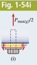
\begin{aligned}P_{f}=\sigma_{ ba 1}(2)\left[\frac{\pi}{4}\left(d_{w}^{2}-d_{1}^{2}\right)\right] &=(65 \ MPa )(2)\left\{\frac{\pi}{4}\left[(28 \ mm )^{2}-(12 \ mm)^{2}\right]\right\} \\&=65.3 \ kN\end{aligned}(g) The allowable shear stress through the clip angle at bolts 1 and 2 is 35 MPa. Each bolt (1 or 2) carries one half of the applied load P (see Fig. 1-54i). The shear area at each bolt is equal to the circumference of the hole (π × d_{w} ) times the thickness of the clip angle (t_{c}). The allowable total load Pg is the the allowable shear stress times twice the shear area:
P_{g}=\tau_{a 1}(2)\left(\pi d_{w} t_{c}\right)=(35 \ MPa )(2)(\pi \times 28 \ mm \times 9.5 \ mm )=58.5 \ kNWe have now found the allowable tensile loads in the hanger based upon all seven of the given conditions. Comparing the seven preceding
results, we see that the smallest value of the load is P_{\text {allow }} = 36.2 kN. This load, which is based upon normal stress in bolts 1 and 2 [see part (e) above], is the allowable tensile load in the hanger.
We could refine the analysis by next considering the self-weight of the entire hanger assembly (see Example 1-6).